|
| |
Chapter 3 Getting Started with Reactis for C
This chapter provides a quick overview of Reactis for C. It contains a brief description of each main component of the tool suite in the form of a “guided-tour” of the different features of the tool suite. Each “stop” in the tour is indicated by a §. The tour uses as a running example a simple automobile cruise control application that is included in the Reactis for C distribution.
| §1 |
To prepare for the tour, copy some files from the Reactis for C distribution to
a local folder:
|
3.1 Quick Start
A typical usage scenario proceeds according to the following steps. The guided tour in the remainder of this chapter describes these operations in more detail.
- Start Reactis for C.
- Select File -> New Build File... to open the Reactis Build File Editor and create a Reactis Build File (.rsm file 1) that lists the C source files that comprise your project.
- Select Edit -> New Harness... to create an execution harness.
An execution harness defines a specific portion of your code to be tested.
The primary components of a harness are an (optional) initialization function,
an (required) entry function,
a set of inputs,
and a set of outputs.
These components determine the structure of the tests constructed by Reactis for C,
which performs the following actions as it constructs a test:
- Call the initialization function.
- Select a value for each input.
- Execute the entry function with the given inputs.
- Record the inputs and resulting outputs as a step in the test.
- If the program has not yet been fully exercised, goto step (b) to add another test step.
The inputs and outputs are either global variables or parameters of the entry function.
- Select Edit -> Inputs... to specify the set of inputs and optionally constrain the set of values an input should assume during testing. For example, you can indicate that a given input should fall within a range (give min/max values) or specify that it should come from an enumerated set of values.
- Select Test Suite -> Create... to generate a test suite (collection of tests) for your execution harness. The resulting test suite will be stored in a Reactis Test Suite file (.rst file). During test creation, runtime errors may be flagged for investigation.
- When test generation completes, dismiss the Reactis Tester dialog and then start Reactis Simulator by selecting Simulate -> Simulator On/Off.
- Load the newly-generated test suite by selecting Test Suite -> Open... and then selecting the new .rst file.
- Execute the whole test suite by selecting Simulate -> Fast Run.
- Examine the source code in the main panel looking for code marked in red to indicate that coverage targets were not exercised by the tests.
3.2 Reactis for C Top Level
The Reactis for C top-level window contains menus and a toolbar for launching testing
and validation activities on C programs. Reactis for C is invoked as follows.
| §2 | Open Reactis for C from the Windows Start menu (or double-click on the desktop shortcut if you installed one). |
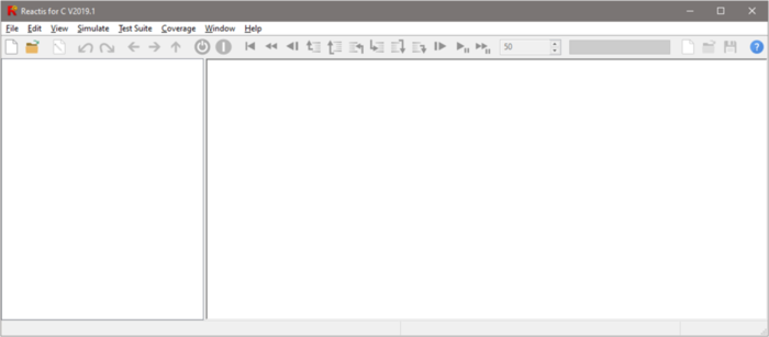
You now see a Reactis for C window like the one as shown in Figure 3.1. A program to be tested is defined by a Reactis Build File (.rsm file) that lists the collection of C source files that comprise the program. The next step creates an .rsm file for the cruise control example.
| §3 |
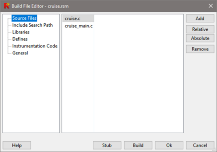
Create cruise.rsm as follows:
|
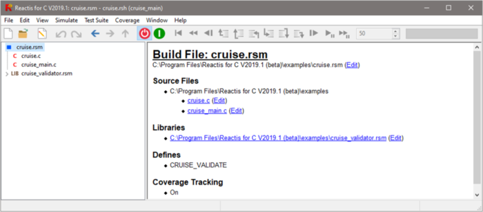
After creating the build file, the top-level window changes as shown in Figure 3.3. The panel to the right shows information about the build file. The panel to the left shows the source files in the project. In addition, the title bar now reports the build file currently loaded, namely cruise.rsm and the Reactis Harness Library (.rsh file ) cruise.rsh that contains test harnesses for testing and validation. Harnesses are created and managed within Reactis for C as explained in the next section.
3.3 The Harness Editor
Reactis for C does not modify any source files in a program. Instead the tool stores project-specific information that it requires in a Reactis Harness Library (.rsh file). The primary way for you to view and edit the data in these files is via the Reactis Harness Editor, which is described briefly in this section and in more detail in Chapter 6.
Next, we will open the the Reactis Harness Editor to examine the inputs that were created for the new harness. When you create a new harness, by default, all pass by value parameters to the entry function are considered inputs, while all pass by reference parameters to the entry function and any return value are considered outputs. You can then modify the set of inputs and outputs inferred from the entry function or tag global variables as inputs or outputs. The default type for each parameter is the base type inferred for the parameter from the program. If you add or remove a parameter to your entry function you can synchronize your .rsh file with the new version of the entry function by selecting Tools -> Synchronize from the Reactis Harness Editor.
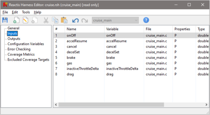
| §5 | To open the harness editor, select Edit -> Inputs.... |
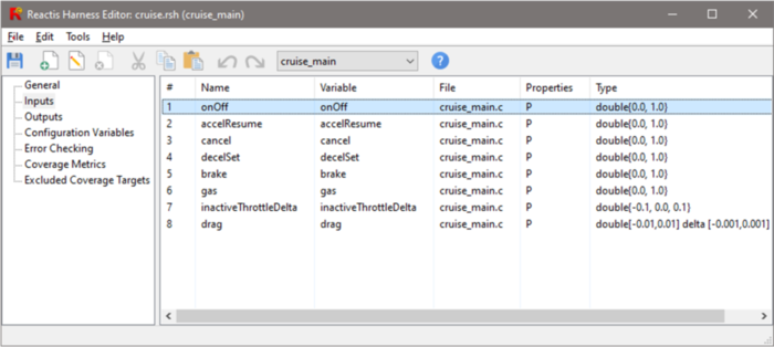
This starts the Reactis Reactis Harness Editor, as shown in Figure 3.4. Note that the contents of the .rsh file may only be modified when Simulator is disabled. When Simulator is running, the Reactis Harness Editor operates in read-only mode as indicated by “[read only]” in the editor window’s title bar.
The Reactis Harness Editor has seven panes:
- General.
- View the harness name, initialization function, and entry function. Modify general parameters such as the sample rate.
- Inputs.
- Add and remove items to the list of inputs and specify type information used by Reactis for C to constrain the set of values fed into inputs during simulation, test-case generation, and C code validation.
- Outputs.
- Add and remove items to the list of outputs.
- Configuration variables.
- Add and remove items to the list of configuration variables, global variables tagged by the user to be changed in between tests in a test suite (but not during a test). The set of values a configuration variable may be assigned during testing may be specified with a type exactly as inputs are.
- Error Checking
- Specify the action to take when an anomalous condition occurs, such as a numeric overflow.
- Coverage Metrics
- Specify which coverage metrics will be tracked during simulation and the details of each metric.
- Excluded Coverage Targets
- Examine targets which are excluded from coverage tracking, and re-enable tracking for some targets.
The types that may be specified are the base Reactis for C types extended with notations to define ranges, subsets and resolutions, and to constrain the allowable changes in value from one simulation step to the next. More precisely, acceptable types can have the following basic forms.
- Complete range of base type:
- By default the type
associated with an input is the base type inferred from
the program. Allowed base types along with their corresponding
C types are as follows:
Reactis Base Type C Type booleanboolint8charuint8unsigned charint16short intuint16unsigned short intint32intuint32unsigned intint32long intuint32unsigned long intsinglefloatdoubledouble - Subrange of base type:
- t[i, j], where t is a base type, and i and j are elements of type t, with i being a lower bound and j an upper bound.
- Subrange with resolution type:
- t [i:j:k],
where t is either
doubleorsingle, i is a lower bound, j is a resolution, and k is an upper bound; all of i, j and k must be of type t. The allowed values that a variable of this type may have are of form i + n × j, where n is a positive integer such that i + n × j ≤ k. In other words, each value that a variable of this type may assume must fall between i and k, inclusive, and differ from i by some integer multiple of j. - Set of specific values:
- t{ e1, … en }, where
t is a base type and e1, … en are
either elements of type t, or expressions of form v:w, where v is an
element of type t and w, a positive integer, is a probability
weight. These weights may be used to influence the relative likelihood
that Reactis will select a particular value when it needs to select a
value randomly to assign to a variable having an enumeration type. If the
probability weight is omitted it is assumed to be “1”.
For example, an input having type
uint{0:1, 1:3}would get the value 0 in 25% of random simulation steps and the value 1 in 75% of random simulation steps, on average. See Chapter 6 for more details. - Delta type:
- t delta [i,j], where t is either a base type, a range type, or a resolution type, and i and j are elements of the underlying base type of t. Delta types allow bounds to be placed on the changes in value that variables may undergo from one simulation step to the next. The value i specifies a lower bound, and j specifies an upper bound, on the size of this change between any two simulation steps. More precisely, if a variable has this type, and v and v′ are values assumed by this variable in successive simulation steps, with v′ the “later” value, then the following mathematical relationship holds: i ≤ v′ − v ≤ j. Note that if i is negative then values are allowed to decrease as simulation progresses.
Table 3.3 gives examples of types and the values they contain.
RSI Type Values in Type double [0.0,4.0]All double-precision floating-point numbers between 0.0 and 4.0, inclusive. int16 [-1,1]-1, 0, 1 int32 {0,4,7}0, 4, 7 uint8 {0:1,1:3}0, 1 double[0.0:0.5:2.0]0.0, 0.5, 1.0, 1.5, 2.0 int16 [0,3] delta [-1, 1]0, 1, 2, 3; inputs of this type can increase or decrease by at most 1 in successive simulation steps.
Table 3.1: Type examples.
| §6 |
In this step we will add constraints for inputs to limit the values selected
for those inputs during test generation.
After adding all the constraints, the result should be similar to Figure 3.5. |
Configuration variables are global variables in your program that you specify should be allowed to change in between tests but not during a test. In the next step of the tour we add a configuration variable.
| §7 |
|
Finally, save the changes and exit the harness editor.
| §8 | From the harness editor’s toolbar select File -> Save to save the harness changes then select File -> Exit to close the Reactis Harness Editor. |
3.4 Instrumentation Code
The final step before simulating and testing is to add some instrumentation code, which will contain code to test specific requirements of the program.
| §9 |
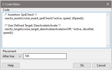
Right-click on line number 106 (click directly on the line number, not on the line itself)
of cruise.c and select Add Instrumentation Code. A window titled C Code Editor
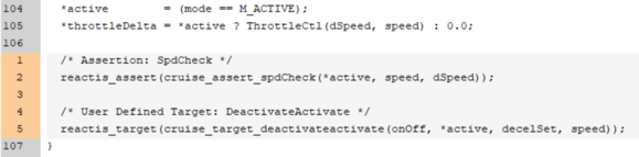
will appear. Type (or copy and paste) the following into the main panel of the editor:/* Assertion: SpdCheck */ reactis_assert(cruise_assert_spdCheck(*active, speed, dSpeed)); /* User Defined Target: DeactivateActivate */ reactis_target(cruise_target_deactivateactivate(onOff, *active, decelSet, speed)); After the text has been entered, the appearance of the dialog should be similar to Figure 3.6. Click the Ok button to close the editor. The instrumentation code should now appear after line 106 of cruise.c, as shown in Figure 3.7. |
You will now need to add instrumentation code in three more places.
| §10 |
After line 4 of cruise.c, add the following:#include "cruise_validator.h" After line 1 of cruise_main.c, add the following: #include "cruise_validator.h" After line 46 of cruise_main.c, add the following: /* User-defined target: Active30 */ reactis_target(cruise_target_active30(*active)); /* User-defined target: LowSpeedOn */ reactis_target(cruise_target_lowspeedon(onOff, *speed)); /* Assertion: Brake */ reactis_assert(!(brake && *active)); /* Assertion: Speed */ reactis_assert(cruise_assert_speed(*speed, *active));
|
Note that there is an asterisk after cruise.rsm in the title bar. This indicates that there are unsaved changes to the instrumentation code. Save the changes now.
| §11 | Select Edit -> Save instrumentation code |
Congratulations! You are now ready to do some simulation and testing.
3.5 Simulator
Reactis Simulator provides a rich array of facilities for viewing the execution of programs.
To continue with the guided tour:
| §12 |
Click the
 (enable Simulator) button in the toolbar
to start Reactis Simulator.
(enable Simulator) button in the toolbar
to start Reactis Simulator.
|
This causes a number of the toolbar buttons that were previously disabled to become enabled.
Simulator performs simulations in a step-by-step manner: for each call to the entry function, values are generated for each input, and after the entry function has executed, the values of the outputs are recorded. You can control how Simulator computes input values with the Source-of-Inputs Dialog in the toolbar (see Figure 3.8) as follows. The tool may be directed to:
- generate values randomly (this is the default);
- query the user;
- read inputs from a Reactis test suite. Such tests may be generated automatically by Reactis Tester, constructed manually in Reactis Simulator, or imported from a file storing test data in a comma-separated-value format.
The next part of the guided tour illustrates the use of each of these input modes. Interspersed with this discussion are asides on coverage tracking, data-value tracking, and other useful features.
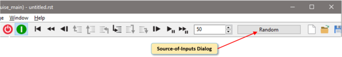
Figure 3.8: The Source-of-Inputs Dialog allows you to control how Reactis Simulator generates values for top-level inputs.
3.5.1 Generating Random Inputs
As the random input source is the default, no action needs to be taken
to set this input mode.
| §13 |
In the panel on the left of the Simulator window,
click on cruise.c in order to display source code in that file.
Then, click the
 (Run/Pause Simulation) button.
When the simulation time (shown in the bottom right corner of the
window) reaches 5, click the
button again to pause
the simulation.
(Run/Pause Simulation) button.
When the simulation time (shown in the bottom right corner of the
window) reaches 5, click the
button again to pause
the simulation.
|
During simulation, lines of code are highlighted in green as they execute. The
simulation stops automatically when the number of simulation steps reaches the
figure contained in the entry box to the left of the Source-of-Inputs Dialog.
Before then, you may halt the simulation by clicking the
(Run/Pause
Simulation) button.
3.5.2 Tracking Code Coverage
While Simulator is running you may track coverage
information regarding which parts of your program have been executed and
which have not. These coverage-tracking features work for all input-source
modes. The next portion of the guided tour illustrates how these features are used.
| §14 | Select menu item Coverage -> Show Summary. |
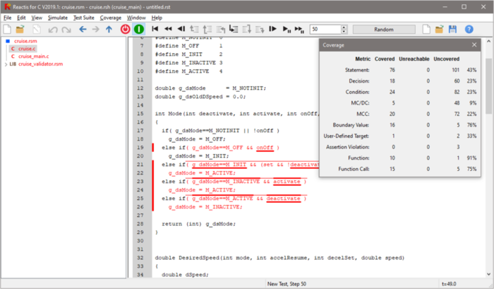
Figure 3.9: The Reactis coverage tracking features convey which parts of a program have been exercised. Note that the coverage information you see at this point will be different than that shown above. This is because a different sequence of inputs (from the random ones you used) brought the simulation to the displayed state.
A dialog summarizing coverage now appears, and elements of the program not yet
exercised are drawn in red, as shown in Figure 3.9. If you see no
red in the main panel, make sure Coverage -> Show Details is selected.
Note that poor coverage is not uncommon with random simulation. A statement is
drawn if red if it has not executed. A thin red line over a decision (e.g.
Boolean expression of an if statement) indicates the decision has never
evaluated to true. A thick red line over a condition (atomic predicate in a
decision) indicates that the condition has not evaluated to true. Similarly,
underlining indicates whether decisions and conditions have evaluated to false.
You may hover over a covered element to determine the (1) test (in the case
being considered here, the “test” is the current simulation run and is
rendered as . in the hovering information) and (2) step within the test
that first exercised the item. This type of test and step coverage information
is displayed with a message of the form test/step. You may view detailed
information for the Condition, Decision and MC/DC coverage
metrics as follows:
| §15 |
Perform the following.
|
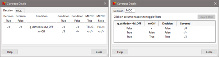
Details for decision coverage, condition coverage, MC/DC and MCC are
conveyed using the tables shown in Figure 3.10.
The left table (Decision tab) in this figure gives information for the decision — g_dsMode==M_OFF && onOff — which includes two conditions — g_dsMode==M_OFF and onOff. Conditions
are the atomic Boolean expressions that are used in decisions. The
first two columns of the table list the test/step information for when
the decision first evaluated to true and when it first evaluated to
false. A value -/- indicates that the relevant situation has not yet
been encountered. The third column lists the conditions that make up the
decision, while the forth and fifth columns give test/step information
for when each condition was evaluated to true and the false.
MC/DC Coverage requires that each condition independently affect the
outcome of the decision in which it resides. When a condition has
met the MC/DC criterion in a set of tests, the sixth and seventh
columns of the table explain how. Each element of these two columns
has the form bb:test/step, where each b reports the
outcome of evaluating one of the conditions in the decision during the
test and step specified. Each b is either T to indicate
the condition evaluated to true, F to indicate the condition
evaluated to false, or x to mean the condition was not
evaluated due to short circuiting.
The right table (MCC tab) in Figure 3.10 displays details of multiple condition coverage (MCC) which tracks whether all possible combinations of condition outcomes for a decision have been exercised. The table includes a column for each condition in the decision. The column header is the condition and each subsequent row contains an outcome for the condition: True, False, or x (indicating the condition was not evaluated due to short-circuiting). Each row also contains the outcome of the decision (True or False) and, when covered, the test and step during which the combination was first exercised.
It should be noted that the previous scenario relied on randomly generated input data, and replaying the steps outlined above will yield different coverage information than that depicted in Figure 3.10
An alternative way to query coverage information is to invoke the
Coverage-Report Browser by selecting Coverage -> Show Report.
This is a tool for
viewing or exporting coverage information that explains which program elements
have been covered along with the test and step where they were first exercised.
A simulation run, and associated coverage statistics, may be reset by clicking
the
 (reset) button in the toolbar.
3.5.3 Reading Inputs from Tests
Simulation inputs may also be drawn from tests in a Reactis test
suite. Such a test suite may be generated automatically by Reactis
Tester, constructed manually in Reactis Simulator, or
imported from a file storing test-data in a comma-separated-value format. By
convention files storing Reactis test suites have a .rst file-name extension.
A Reactis test suite may be loaded into Simulator as follows.
| §16 |
Click the
 button in the toolbar to the right of the
Source-of-Inputs Dialog and use the file-selection dialog to select
button in the toolbar to the right of the
Source-of-Inputs Dialog and use the file-selection dialog to select
cruise.rst in the examples folder of the Reactis for C
distribution.
|
This causes cruise.rst, the name of a test suite file generated
by Reactis Tester, to appear in the title bar and the contents of the
Source-of-Inputs Dialog to change; it now contains a
list of tests that have been loaded. To view this list:
| §17 | Click on the Source-of-Inputs Dialog. |
Each test in the suite has a row in the dialog that contains a test
number, a sequence number, a name, and the number of steps in the test.
Clicking the “all” button in the lower left corner specifies that
all tests in the suite should be executed one after another. To
execute the last test in the suite:
| §18 |
Do the following.
|
If you look at the bottom-right corner of the window, you can see that
the test is being executed, although the results of each execution
step are not displayed graphically. When the test execution
completes, the exercised parts of the C code are drawn in black. If
the Run Simulation button (
) is clicked instead,
then the results of each simulation step are rendered graphically,
with the consequence that simulation proceeds more slowly.
You may specify that a subset of tests should be run by holding down the control key and clicking on each test to be run in the Source-of-Inputs Dialog with the left mouse button. The tests will be run in the order they are selected. As tests are selected, the sequence number column is updated to indicate the execution order of the tests.
You may also use the Source-of-Inputs Dialog to change the name of a test. To do so, select the test by single clicking on it, then click on the name and, when the cursor appears, type in a new name and press return.
3.5.4 Tracking Values of Data Items
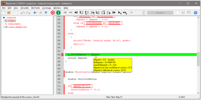
As shown in Figure 3.11, when Simulator is paused at a breakpoint, you may view the current value of a given variable by hovering over the variable with your mouse cursor.
You may also select data items whose values you wish to track during
simulation using the watched-variable and
scope facilities ofSimulator.
| §19 |
Navigate to the Cruise function in cruise.c, then right-click on the
variable “mode” and select Add to Watched from the resulting pop-up menu.
|
The bottom of the Simulator window now changes to that indicated in Figure 3.12.
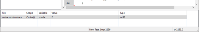
Figure 3.12: The watched-variable panel in Simulator displays the values of data items, as does hovering over a data item with the mouse.
The watched-variable panel shows the values of watched data items in the current simulation step, as does hovering over a data item with the mouse. Variables may be added to, and deleted from, the watched-variable panel by selecting them and right-clicking to obtain a menu. You may also toggle whether the watched-variable list is displayed or not by selecting the View -> Show Watched Variables menu item.
| §20 |
Repeatedly click
 (step into) to execute a single statement at a time.
Observe how the value displayed in the watched variable panel changes from
[out of scope], to [not initialized], to a value.
(step into) to execute a single statement at a time.
Observe how the value displayed in the watched variable panel changes from
[out of scope], to [not initialized], to a value.
|
Scopes display the values a given global variable has had at the end of each
step since the beginning of the current simulation run. To open a scope:
| §21 | In the main panel, scroll to the top of cruise.c, right-click in variable g_dsMode and select Open Scope from the resulting pop-up menu. |
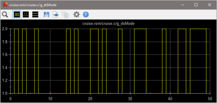
Figure 3.13: A scope window plotting the mode of the cruise control during a test. Note that the plots you see will be different than that shown above. This is because a different sequence of inputs brought the simulation to the displayed state.
| §22 | Close the watched-variable panel by selecting the View -> Show Watched Variables menu item. |
3.5.5 Querying the User for Inputs
The third way for Simulator to obtain values for input parameters
is for you to provide them. To enter this mode of
operation:
| §23 | Select User Guided Simulation from the Source-of-Inputs Dialog. |
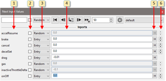
Upon selecting this input mode, a Next Input Values dialog appears, as shown in Figure 3.14, that allows you to specify the input values for the next simulation step. Each input has a row in the dialog containing five columns; these determine the next input value for the corresponding parameter as follows.
- The input name.
- The column 2 pull-down menu has entries that determine
how the next value for the parameter is specified:
- Random
- Randomly select the next value for the input from the type given for the input in the .rsh file.
- Entry
- Specify the next value with the text-entry box in column three of the row.
- Panel
- Open a separate dialog to control the input.
- If the pull-down menu in column two is set to “Entry”, then the next input value is taken from this text-entry box.
- If the pull-down menu in column two is set to “Entry”, then clicking the history button (labeled H) displays recent values the input has assumed. Selecting a value from the list causes it to be placed in the text-entry box of column three.
- The arrow buttons in this column enable you to scroll through the possible values for the parameter. The arrows are not available for parameters of type double or single or ranges with a base type of double or single.
When Run Simulation (
) or Run Fast
Simulation (
 ) is selected, the input values specified
are used for each subsequent simulation step until the simulation is paused.
) is selected, the input values specified
are used for each subsequent simulation step until the simulation is paused.
3.5.6 Other Features
Simulator has several other noteworthy features. You may step both forward and backward through a simulation using toolbar buttons:
- The
 button executes a single step, i.e. a single
execution of the harness entry function.
button executes a single step, i.e. a single
execution of the harness entry function. - The
button executes a single C statement, perhaps
stepping into the body of a function being called.
- When execution is paused at a function call, the
 button
executes the function, then pauses after the function returns.
button
executes the function, then pauses after the function returns. - The
 button completes the execution of the currently
executing function.
button completes the execution of the currently
executing function. - The
 button steps back by a single C statement, perhaps
stepping back into a function that was called immediately before the current
statement.
button steps back by a single C statement, perhaps
stepping back into a function that was called immediately before the current
statement. - When execution is paused after a function call, the
 button steps back without stepping into the function.
 - The
 button steps back to the statement that called
the currently executing function.
button steps back to the statement that called
the currently executing function. - The
 button, which causes the simulation to go back
(undo) a single step or go back to the beginning of the current step.
button, which causes the simulation to go back
(undo) a single step or go back to the beginning of the current step. - The
 button causes the simulation to go back multiple
steps.
button causes the simulation to go back multiple
steps.
You may specify the number of steps taken when
,
, or
are pressed by adjusting the number in
the text-entry box to the right of
.
When a simulation is paused at the end of a
simulation step (as opposed to in the middle of a simulation step),
the current simulation run may be added to the current test suite by
selecting the menu item Test Suite -> Add/Extend Test.
When the test is added, it appears in the Source-of-Inputs Dialog.
After saving the
test suite with Test Suite -> Save, the steps in the new test
may be viewed by selecting Test Suite -> Browse .
Breakpoints may be toggled on lines within a C file
which contain an executable C statement by double-clicking just to the right of
the line number, or by right-clicking to the right of the line number and
selecting Toggle Breakpoint. The
 symbol is drawn to the right of
a line number when a break point is set. During a simulation run, whenever a
breakpoint is hit Simulator pauses immediately. When paused at a breakpoint,
you may proceed either by:
symbol is drawn to the right of
a line number when a break point is set. During a simulation run, whenever a
breakpoint is hit Simulator pauses immediately. When paused at a breakpoint,
you may proceed either by:
-
executing one or more statements at a time with
,
,
- reverse executing one or more statements at a time with
,
,
- completing the current simulation step by clicking
.
- returning to the beginning of the current step by clicking
.
In either case, after reaching the end of the current simulation step, all other navigation buttons in the toolbar become enabled.
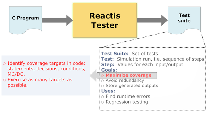
3.6 Tester
Tester may be used to generate a test suite (a set of tests) automatically from a C program as shown in Figure 3.15. The tool identifies coverage targets in the C code and aims to maximize the number of targets exercised by the generated tests.
To start Tester:
| §24 | Select the Test Suite -> Create menu item. |
This causes the Tester launch dialog shown in Figure 3.16 to appear. The first section of the dialog (Preload Files) lists previously-generated test suites to be pre-loaded. The second section (Run for) determines how long tester should run. The third section (Coverage Objectives) lists the metrics which Tester will focus on during the targeted testing phase. In the fourth section, you specify the name of the output file in which Tester will store the new test suite (Output File).
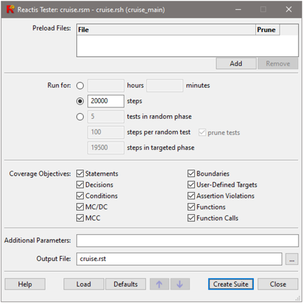
There are three options provided in the Run for section. The default option, as shown in Figure 3.16, is to run Tester for 20000 steps. Alternatively, you may choose to run Tester for a fixed length of time by clicking on the top radio button in the Run for section, after which the steps entry box will be disabled and the hours and minutes entry boxes will be enabled. These values are added together to determine the total length of time for which Tester will run, so that entering a value of 1 for hours and 30 for minutes will cause Tester to run for 90 minutes. In most cases either the first or second option is preferred. For a description of the third option, see Chapter 9.
The Coverage Objectives section contains check boxes which are used to select the kinds of targets Tester will focus on during the targeted testing phase. Chapter 7 describes the different types of coverage tracked by Reactis.
To generate a test suite in the guided tour, retain the default
settings and:
| §25 | Click the Create Suite button. |
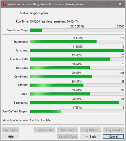
The Tester progress dialog, shown in Figure 3.17, is displayed during test-suite generation. When Tester terminates, a results dialog is shown, and a file cruise.rst containing the suite is produced. The results dialog includes buttons for loading the test suite into the Test-Suite Browser (see below), or Reactis Simulator.
3.7 The Test-Suite Browser
The Test-Suite Browser is used to view the test suites created by Reactis for C. It may be invoked from either the Tester results dialog or the Reactis for C top-level window.
| §26 | Select the Test Suite -> Browse menu item and then cruise.rst from the file selection dialog that pops up. |
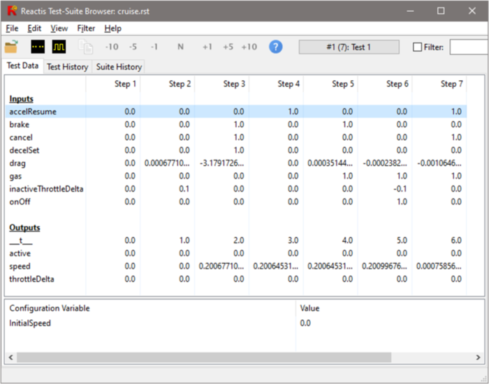
A Test-Suite Browser window like the one shown in Figure 3.18 is
then displayed. The Test Data tab of the browser displays
the test selected in the button/dialog located near the center of the
browser’s toolbar. The main panel in the browser window shows the
indicated test as a matrix, in which the first column gives the names of
the harness inputs and outputs and each subsequent column lists the values
for each input or output for the corresponding simulation step. The
simulation time is displayed in the output row labeled “___t___”.
The buttons on the toolbar may be used to scroll forward and backward in
the test. The Test History and Suite History tabs
display history information recorded by Reactis for the test and the
suite as a whole.
The Filter entry box on the right side of the toolbar lets you search
for test steps that satisfy a given condition. You enter a Boolean expression
in the search box and then select the filter check box to search for test steps
in the suite for which the expression evaluates to true. For example, to see
each step where the cruise control is active enter “active == 1” and
then select the Filter check box.
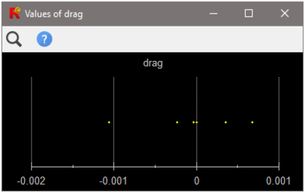
The Test-Suite Browser offers distribution scopes to display the entire set of values
assumed by an input or output during a single test or set of tests.
| §27 |
Perform the following in the Test-Suite Browser window.
|
A dialog similar to that shown in Figure 3.19 appears. In the figure, each value assumed by the input drag is represented by a yellow dot.
3.8 Validator
Reactis Validator is used for checking whether programs behave correctly. It enables the early detection of design errors and inconsistencies and reduces the effort required for design reviews. The tool gives you two major capabilities.
- Assertion checking.
- You can instrument your code with assertions, which monitor code behavior for erroneous scenarios. If Reactis detects an assertion violation, it returns a test highlighting the problem. This test may be executed in Reactis Simulator to uncover the source of the error.
- Test scenario specifications.
- You can also instrument your code with user-defined targets, which may be used to define test scenarios to be considered in the analysis performed by Tester and Validator. Like assertions, user-defined targets also monitor code behavior; however, their purpose is to determine when a desired test case has been constructed, so that the test may be included in a test suite.
Conceptually, assertions may be seen as checking system behavior for potential errors, user-defined targets monitor system behavior in order to check for the presence of certain desirable executions (tests).
The following methods can be used to track assertions:
-
Add standard C
assertstatements in the code and enable the Create coverage targets for assert() statements setting in the Reactis Settings dialog. Reactis will then track theassertcalls as Reactis assertions instead of raising an exception if the assertion fails. - Add
reactis_assertstatements in your code and add a directive:#include <reactis_validator.h>
at the top of the source file. Reactis will count the assertion as violated if the argument to thereactis_assertcall is zero.
To track user-defined targets, add reactis_target statements in your
code and add a directive:
#include <reactis_validator.h>
at the top of the source file. Reactis will count the target as covered if the
argument to the \reactis_target call is non-zero.
- 1
- Reactis Build Files were previously called Reactis Makefiles, hence the file suffix .rsm. The more generic “Build File” notation was adopted to distinguish from the specific Unix/GNU Make build environment.