Chapter 6 Reactis Coverage Metrics
Reactis uses a number of different coverage metrics on Simulink / Stateflow models to measure how thoroughly a test or set of tests exercises a model. In general, coverage metrics record how many of a given class of syntactic constructs, or coverage targets, that appear in a model have been executed at least once. Some of the metrics supported by Reactis involve only Simulink, some are specific to Stateflow, and the remaining are generic in the sense that they include targets within both the Simulink and the Stateflow portions of a model. When using the Reactis for C Plugin, coverage targets are also tracked in the C code portions of models (S-Functions and Stateflow custom C code). Additionally, when using the Reactis for EML Plugin, coverage targets are tracked within any Embedded MATLAB code used by a model. The metrics discussed in this chapter may be visualized using Simulator and are central to test generation and model validation using Tester and Validator.
6.1 Simulink-Specific Metrics
The Simulink-specific metrics include the following: conditional subsystem coverage, branch coverage, and lookup table coverage.
6.1.1 Conditional Subsystem Coverage
A (conditional) subsystem is deemed covered if has been executed at least once in some simulation step. In general, every subsystem within a Simulink diagram executes during every simulation step. However, conditional subsystems may be disabled during a simulation step and hence not execute.
6.1.2 Branch Coverage
A number of different Simulink blocks contain targets included in the branch coverage measure. Each block in this group has the characteristic that the set of all possible outcomes of evaluating the block may be partitioned into well-defined sets of mutually exclusive outcomes. For example, the possible outcomes of evaluating a Logical Operator block are true or false. Therefore, for each Logical Operator block, we consider the true outcome and the false outcome to be the two branches associated with the block. Each branch becomes a coverage target in the branch-coverage metric.
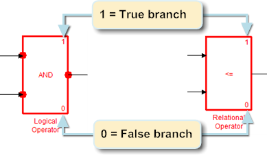
The following discusses branch coverage in more detail. Reactis Tester aims to exercise all such branches in the test suites it generates. Reactis Simulator includes several ways to track the branches that have been exercised. In particular, in model diagrams, every block that includes branches is drawn in a way to show each branch and uncovered branches are drawn in red. We now list the blocks included in the branch-coverage metric; for each block, we describe its associated branches and how coverage information for the branches is drawn in Simulator.
- Logical Operator.
- The branches are:
- the block evaluates to true
- the block evaluates to false
- Relational Operator.
- The branches are:
- the block evaluates to true
- the block evaluates to false
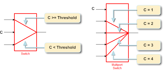
- Switch.
- Let C be the condition for passing the first input of a Switch block; i.e.
C is u2 ≥ threshold, u2 > threshold, or u2
~=0. Then the branches are:- C evaluates to true.
- C evaluates to false.
- Multiport Switch.
- If a Multiport switch has n data inputs, then it is considered to have n branches, one for each data input. Branch i is covered when the control input has value i during evaluation of the block.
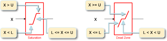
- Dead Zone.
- Let X be the input to, L the lower limit of, and U the upper
limit of a Dead Zone block. Then the branches are:
-
X
<=L - L < X < U
- X
>=U
-
X
- Saturation.
- Let X be the input to, L the lower limit of, and U the upper limit of
a Saturation block. Then the branches are:
- X < L
- L
<=X<=U - X > U
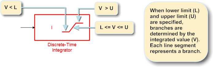
- Discrete-Time Integrator.
- Let V be the integrated value, L the lower limit of, and
U the upper limit of
a Discrete-Time Integrator block. Then the branches are:
- V < L
- L
<=V<=U - V > U
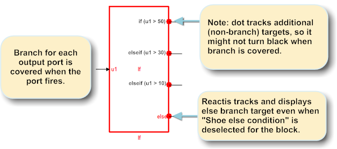
- If.
- The Block Parameters dialog for the If block includes a
“Show else condition” check box that determines whether or not the
block includes an output port for the else case of the block. The
definition of the branches for this block differ slightly depending on
the value of this setting.
- If an If block has n outputs and the “Show else condition” check box is selected, then the block is considered to have n branches, one for each output. Branch i is covered when the system connected to output i executes.
- If an If block has n outputs and the “Show else condition” check box is not selected, then the block is considered to have n + 1 branches, one for each output and one for the implicit else case. For branches 1 to n, branch i is covered when the system connected to output i executes. Branch n + 1 is covered when the If block executes, but no output fires (that is when the implicit else case is taken).
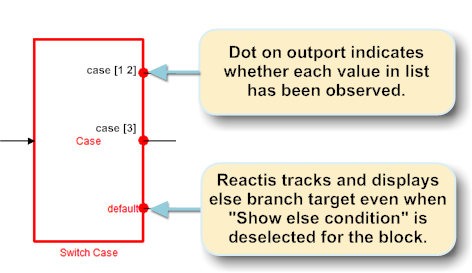
- Switch Case.
- The Block Parameters dialog for the Switch Case block includes a “Show default case” check box that determines whether or not the block includes an output port for the default case. Reactis tracks a branch for the default case whether or not this check box is selected. Additionally the parameters of this block define a sequence of integer sets 1 S1, S2, ..., Sn. Each set is associated with an output of the block. Reactis tracks a branch target for each element of each set Si. A branch value n in set Si is covered if the control input to the block is n and the outport associated with Si fires.
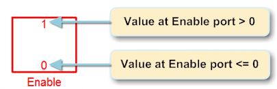
- Enable.
- Let X be the input to an Enable port of the subsystem S in which
the Enable block resides. Then the branches are:
- X > 0 - subsystem S executes
- X ≤ 0 - subsystem S does not execute
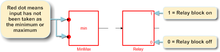
- MinMax.
- If a MinMax block has n inputs, then it is considered to have n branches, one for each input. Branch i is covered when input i is selected as the minimum or maximum value of inputs to the block.
- Relay.
- The branches are
- The relay is on.
- The relay is off.
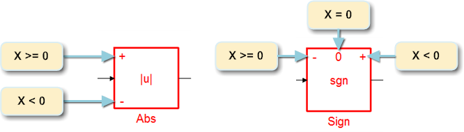
- Abs and Sign blocks.
- Let X be the input to an Abs block.
Then the branches are:
- X ≥ 0
- X < 0
Let X be the input to a Sign block. Then the branches are:
- X > 0
- X = 0
- X < 0
6.1.3 Lookup Table Coverage
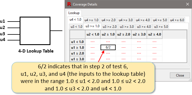
Reactis supports coverage tracking for the 1-D Lookup Table, 2-D Lookup Table, n-D Lookup Table, Prelookup, and Interpolation Using Prelookup blocks that are configured for 1-4 dimensions. Intuitively a coverage target will be allocated for each interval specified by the breakpoint settings of a table. To view the coverage information for a table in Simulator, right-click on the table and select View Coverage Details.
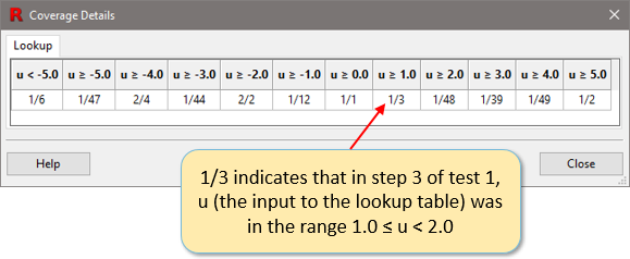
6.1.3.1 1-D Lookup Table
If a 1-D Lookup Table block has inport u and breakpoints [ u1, u2, ... , un ] then the block will have the following targets:
| u < u1 | u1 ≤ u < u2 | u2 ≤ u < u3 | ... | un−1 ≤ u < un | u ≥ un |
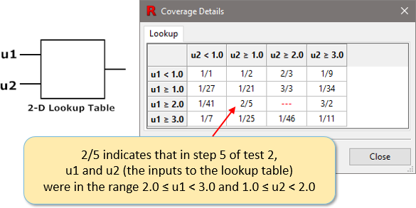
6.1.3.2 2-D Lookup Table
If a 2-D Lookup Table block has inputs u1 and u2,
“Breakpoints 1” [ r1, r2, ... , rm ], and
“Breakpoints 2” [ c1, c2, ... , cn ] then the block
will have the following targets:
| u1 < r1 and u2 < c1 | u1 < r1 and c1 ≤ u2 < c2 | u1 < r1 and c2 ≤ u2 < c3 | ... | u1 < r1 and cn−1 ≤ u2 < cn | u1 < r1 and u2 ≥ cn |
| r1 ≤ u1 < r2 and u2 < c1 | r1 ≤ u1 < r2 and c1 ≤ u2 < c2 | r1 ≤ u1 < r2 and c2 ≤ u2 < c3 | ... | r1 ≤ u1 < r2 and cn−1 ≤ u2 < cn | r1 ≤ u1 < r2 and u2 ≥ cn |
| r2 ≤ u1 < r3 and u2 < c1 | r2 ≤ u1 < r3 and c1 ≤ u2 < c2 | r2 ≤ u1 < r3 and c2 ≤ u2 < c3 | ... | r2 ≤ u1 < r3 and cn−1 ≤ u2 < cn | r2 ≤ u1 < r3 and u2 ≥ cn |
| ⋮ | |||||
| rm−1 ≤ u1 < rm and u2 < c1 | rm−1 ≤ u1 < rm and c1 ≤ u2 < c2 | rm−1 ≤ u1 < rm and c2 ≤ u2 < c3 | ... | rm−1 ≤ u1 < rm and cn−1 ≤ u2 < cn | rm−1 ≤ u1 < rm and u2 ≥ cn |
| u1 ≥ rm and u2 < c1 | u1 ≥ rm and c1 ≤ u2 < c2 | u1 ≥ rm and c2 ≤ u2 < c3 | ... | u1 ≥ rm and cn−1 ≤ u2 < cn | u1 ≥ rm and u2 ≥ cn |
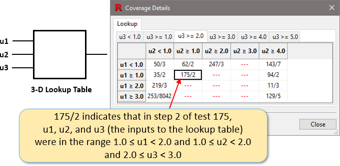
6.1.3.3 n-D Lookup Table (3 Dimensions)
If a n-D Lookup Table block has 3 dimensions and inputs u1, u2, and u3 with respective breakpoints [a1, a2, ..., am], [b1, b2, ..., bn], and [c1, c2, ..., co] then the block will have the following targets:
u1 < a1 and u2 < b1 and u3 < c1
u1 < a1 and u2 < b1 and c1 ≤ u3 < c2
u1 < a1 and u2 < b1 and c2 ≤ u3 < c3
...
u1 ≥ am and u2 ≥ bn and u3 ≥ co
6.1.3.4 n-D Lookup Table (4 Dimensions)
If a n-D Lookup Table block has 4 dimensions and inputs u1, u2, u3, and u4 with respective breakpoints [a1, a2, ..., am], [b1, b2, ..., bn], [c1, c2, ..., co], and [d1, d2, ..., dp] then the block will have the following targets:
u1 < a1 and u2 < b1 and u3 < c1 and u4 < d1
u1 < a1 and u2 < b1 and u3 < c1 and d1 ≤ u4 < d2
u1 < a1 and u2 < b1 and u3 < c1 and d2 ≤ u4 < d3
...
u1 ≥ am and u2 ≥ bn and u3 ≥ co and u4 ≥ dp
6.2 Stateflow-Specific Metrics
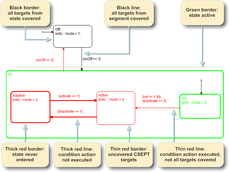
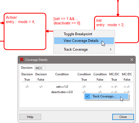
The Stateflow metrics are defined with respect to the graphical syntax of Stateflow. Among other things, Stateflow diagrams contain states, transition segments, and junctions. Each transition segment in turn may have a label that includes all or some of the following: an event, a condition, a condition action, and a transition action. A segment’s condition action is executed whenever the segment’s condition evaluates to true. A transition consists of a sequence of segments leading from one state to another. The transition will fire when the condition on each segment in the sequence evaluates to true. A segment’s transition action is executed only when it is included in such a firing transition. Highlighting of coverage in Stateflow diagrams is shown in Figure 6.14. Note that in addition to the Stateflow-specific metrics, decision, condition, MC/DC and MCC coverage targets may be associated with transition segments.
6.2.1 State Coverage
The targets in this metric are states; a state is covered if it has been entered at least once.
6.2.2 Condition Action Coverage
The targets in this metric are transition segments; a segment is deemed to be covered if its condition action has been executed at least once, or, if the segment has no condition action, if its condition has evaluated to “true” at least once. Note that a segment with an empty condition is assumed to have a condition that always evaluates to “true” when the segment is considered for inclusion in a firing transition during model execution.
6.2.3 Transition Action Coverage
The targets in this metric are transition segments that have transition actions; such a segment is deemed to be covered if its transition action has been executed at least once. Note that if a segment has no transition action, it is ignored by this metric.
6.2.4 Child State Exit via Parent Transition
Consider the Stateflow diagram in Figure 6.14. The state On has three child states: Inactive, Active, and Init. Child State Exit via Parent Transition (CSEPT) coverage tracks whether the transition from On to Off has fired while On is in each of its child states. So in this case there are three CSEPT targets. Namely the transition from On to Off fires when:
- On is in state Inactive
- On is in state Active
- On is in state Init
More precisely, a Stateflow state S has the following CSEPT targets:
- If S is a top-level state (it has no parent), then S has no CSEPT targets.
- If Parent(S) is the parent of S, then for every transition that causes Parent(S) to exit, S has a corresponding CSEPT target.
If your model has states nested deeper than one level (e.g. Parent(S) has a parent for some state S) or a transition causing Parent(S) to exit has multiple transition segments, then you can adjust the definition of CSEPT targets with two settings that you specify in the Coverage tab of the Info File Editor (see Section 5.10) . These settings specify which states and transitions will be paired with a state to form CSEPT targets. In the following:
- PairStates(S) is the set of states paired with S to define the CSEPT targets of S
- ExitTrans(S′) is the set of either transition segment sequences or single transition segments that cause a state S′ to exit.
The two settings you control indicate the following definitions for PairStates and ExitTrans:
- CSEPT States
- can be set to All ancestors or Parent only:
- All ancestors
- PairStates(S) = Ancestors(S) where S″ ∈ Ancestors(S) if S″=Parent(S) or there exists S′ ∈ Ancestors(S) such that S″ = Parent(S′).
- Parent only
- PairStates(S) = Parent(S).
- CSEPT Transitions
- can be set to Full transition paths or
First segment only:
- Full transition paths
- ExitTrans(S′) = all transition segment sequences that form a complete transition that can fire and cause S′ to exit.
- First segment only
- ExitTrans(S′) = all transition segments that are the first segment of a transition sequence that can fire and cause S′ to exit
These options yield a parameterized definition of CSEPT targets. A Stateflow state S has the following CSEPT targets:
- If S is a top-level state (it has no parent), then S has no CSEPT targets.
- For every state S′ in PairStates(S), for every transition T in ExitTrans(S′), S has a corresponding CSEPT target.
6.3 Generic Metrics
Generic coverage metrics define targets which may appear in the Simulink, the Stateflow, the Embedded MATLAB 2, or the C code 3 portions of a model. There are six generic coverage metrics supported by Reactis: (1) decision coverage, (2) condition coverage, (3) modified condition/decision coverage (MC/DC), (4) multiple condition coverage (MCC), (5) boundary coverage, and (6) interval coverage. The first five metrics are are based on well-known coverage metrics of the same names developed for measuring coverage of source code. Interval coverage is unique to Reactis.
6.3.1 Decision, Condition, MC/DC and MCC Metrics
Reactis includes facilities for generating tests to meet the decision, condition, modified condition/decision coverage (MC/DC) and multiple condition coverage (MCC) requirements. Each of these metrics involve boolean-valued structures (conditions, decisions) within a model; understanding these metrics requires that the notions of conditions and decisions be defined precisely. As the notions were first developed in the context of traditional programming languages (e.g. C, Ada), the next paragraphs first review their traditional definitions. The adaptations of these notions to Simulink and Stateflow are then discussed.
In software testing, a decision is a boolean-valued expression used to determine which execution path to follow, and a condition is a boolean-valued sub-expression of a decision which cannot be broken into smaller boolean sub-expressions because it does not contain any boolean operators. Decisions are typically constructed by using boolean operators to combine several conditions. For example, consider the following statement from a C program:
    if ((x > 0) && (y > 0))
       z = 1;
    else
       z = 2;
Here ((x > 0) && (y > 0)) is a decision, since the value of the
expression determines whether z is assigned the value 1 or 2. Both
(x > 0) and (y > 0) are conditions, since they are
boolean-valued expressions that cannot be broken into smaller boolean expressions.
Traditional decision coverage may now be defined as follows. Each decision in a program gives rise to two targets: the evaluation of the decision to true, and to false; a program is fully covered by a test suite when each target has been covered, i.e. each decision has evaluated to both true and false. Condition coverage is defined very similarly; the difference is that each condition evaluates to both true and false, rather than each decision.
MC/DC is somewhat more complex to define. It was introduced by John J. Chilenski of Boeing in the early 90s; the definitive research paper was published by Chilenski and Steve Miller, of Rockwell-Collins, in 1994. MC/DC is the level of testing mandated by the Federal Aviation Administration (FAA) in its DO-178/B guidelines for the “most safety-critical” components of aviation software. The metric was subsequently adopted in the ISO 26262 safety standard for automotive software. The MC/DC targets in a program are the conditions; a condition C in decision D is covered by a test suite if there are two test steps X and Y (not necessarily consecutive) in the suite such that:
- C evaluates to a different truth value (true or false) in step X than in step Y; and
- each condition other than C in D evaluates to the same truth value in both step X and step Y; and
- D evaluates to a different truth value in step X than in step Y.
In other words, each condition must be shown to independently affect the outcome of its enclosing decision.
Multiple Condition Coverage (MCC, also known as Condition
Combination Coverage) tracks one target for each combination of
values to which the conditions in a decision evaluate. For a decision
with N conditions this will create 2N MCC targets. A decision
D = C1 && C2 && C3 will need 8 MCC targets to track all possible
combinations of C1, C2, and C3 (each row in the table below
represents one MCC target):
| C1 | C2 | C3 | D |
| false | false | false | false |
| false | false | true | false |
| false | true | false | false |
| false | true | true | false |
| true | false | false | false |
| true | false | true | false |
| true | true | false | false |
| true | true | true | true |
Short-circuiting of boolean expressions can affect the difficulty of
achieving full MC/DC or MCC coverage of a program. A short-circuited
operator avoids evaluating all conditions of a decision if the outcome
is determined after evaluating only a subset of the conditions. For
example, a short-circuited “and” operator would not evaluate its
second argument if the first evaluates to false. Virtually all
programming languages use short-circuiting for reasons of efficiency.
Without going into the technical details, it can be said that
achieving full MC/DC coverage is easier if short-circuited boolean
operators are used. For MCC coverage, short-circuited expressions
generate a reduced number of coverage targets compared to
non-short-circuited expressions. The D = C1 && C2 && C3 decision
creates only 4 (as opposed to 8) MCC targets (the x
characters in the table below represent “don’t care” terms - conditions
that were not evaluated due to short-circuiting and whose value
therefore can not be recorded):
| C1 | C2 | C3 | D |
| false | x | x | false |
| true | false | x | false |
| true | true | false | false |
| true | true | true | true |
Section 4.8.1 explains how Reactis may be instructed to treat Simulink / Stateflow boolean operators as short-circuited.
In order to adapt the notions of decision, condition, MC/DC and MCC coverage to Simulink / Stateflow, it suffices to define what the conditions and decisions in a model are. These are as follows.
- For Logical Operator blocks, Reactis supports two alternative modes for
tracking decision, condition, MC/DC and MCC coverage.
The mode is set from the
Coverage pane of the Info File Editor (see
Section 5.10).
The two modes are single-block and multi-block. In the former, a decision is a single logical operator block; while in the latter, several logical operator blocks may be grouped into a single decision. To understand the difference between the two modes, consider the following model fragment:
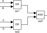
In single-block mode, this fragment includes three separate decisions; each with its own conditions, MC/DC and MCC targets:
Decisions Conditions A or B A, B C or D C, D op1 and op2 op1, op2 When multi-block decision coverage is enabled, these three operators are combined into a single decision:
Decisions Conditions A or B and C or D A, B, C, D When multi-block decision coverage is enabled, hovering over a Logical Operator block will show arrows indicating the group to which the block belongs. If no arrows appear, then the block is not part of any group.
The definition of decisions and conditions for the two modes are as follows.
- Single-Block.
- The output of each Logical Operator block is a decision and its inputs constitute the conditions within the decision.
- Multi-Block.
-
Multiple Logical Operator blocks that are directly connected are grouped
into a single decision. The inputs to blocks in the group that are not
connected to the outputs of other blocks in the group constitute the
conditions of the decision.
When multi-block decision coverage is enabled, the following rules are used to combine the Logical Operator blocks of a model into groups, each of which constitutes a single decision:
- Groups may only contain Logical Operator blocks.
- Groups may not cross subsystem boundaries.
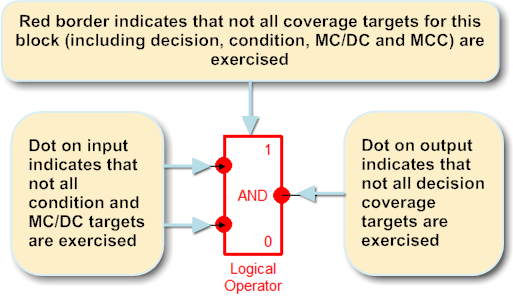
- Each group has exactly one exiting signal line. The output port of the block at which the exiting signal line originates will be marked as the decision. A red dot on the output port indicates that the decision has not evaluated to both true and false. The coverage details table for the decision may be invoked by right-clicking on the output port and selecting View Coverage Details. Hovering over the block causes blue lines to be drawn from each condition in the decision to the output port.
- Each group may have multiple incoming signal lines. The input ports of the blocks where the entering signal lines end will be marked as the conditions of the decision. A red dot on one of the inports implies that the port has an uncovered condition or MC/DC target.
- The set of Logical Operator blocks L within a subsystem is
partitioned into a set of groups as follows. If the output of a
Logical Operator block l ∈ L feeds into any block other than
another Logical Operator block or the output of l is monitored
by a Reactis test point, then l is the root of a group.
The set of blocks contained in the group rooted at a block r,
denoted G(r) is defined as:
- r ∈ G(r)
- If l ∈ L and all branches of the output of l feed into a block l′ ∈ G(r) and the output of l is NOT monitored by a Reactis test point, then l ∈ G(r)
- The “if expression” and “elseif expressions” within an If block in Simulink are decisions. In this case, the atomic boolean-valued sub-expressions are the conditions.
- Recall that Stateflow transitions may have a label of the form:
event[guard]{condition action}/transition action.Note that for this discussion we use the term “guard” rather than “condition” for the boolean expression in braces to avoid confusion with the use of that word in context of MC/DC, decision, and condition coverage. Theevent[guard]combinations on Stateflow transitions are considered decisions. They evaluate to true if the event is present and the guard is true, and to false otherwise. The conditions within the decision associated with a transition segment are:- If the label includes an event, then the event is a condition. The condition is “true” if it is present and “false” otherwise.
- The atomic Boolean-valued expressions in the guard are also conditions.
- When using the Reactis for C Plugin, additional decisions are tracked as described in Chapter 16 .
- When using the Reactis for EML Plugin, additional decisions are tracked as describe in Chapter 17 .
Coverage information for decision, condition, and MC/DC coverage is rendered as shown in Figure 6.15. Right-clicking on an outport of a Logical Operator block and selecting View Coverage Details gives additional information.
6.3.2 Boundary Value Coverage
Boundary Value Coverage tracks whether a data item assumes values of interest for a particular block. In the case of harness model inports, test points, and configuration variables, these are the boundary values of the item’s domain of possible values. In the case of a Relational Operator block, the values of interest occur when the two inputs to the block are equal or very close.
6.3.2.1 Boundary Values for Inports, Test Points, and Configuration Variables
The boundary values tracked for an inport, test point, or configuration variable are determined by its associated type constraint 4 as shown in Table 6.1. If an inport or configuration variable has a type not shown in the table, then it has no boundary value targets.
RSI Type Boundary Values t[i, j], where t is double, single, sfix*, or ufix* if i < 0 and j > 0 then i, 0.0, j; otherwise i, j t[i, j], where t is and integer type if i < 0 and j > 0 then i, i+1, 0, j−1, j; otherwise i, i+1, j−1, j t{ e1, … en } e1, … en t [i:j:k] if there exists a positive integer l such that i + l × j = 0.0 then i, i+j, 0.0, k−j, k; otherwise i, i+j, k−j,k t delta [i,j] boundary values of t boolean true, falseint8 -128, -127, 0, 126, 127 int16 -32768, -32767, 0, 32766, 32767 int32 -2147483648, -2147483647, 0 2147483646, 2147483647 uint8 0, 1, 254, 255 uint16 0, 1, 65534, 65535 uint32 0, 1, 4294967294, 4294967295 sfix* let S, B, W be the total slope, bias and width (in bits) of the type, i = −(2W−1) × S + B and j = (2W−1−1) × S + B: if i < 0 and j > 0 then i, 0.0, j; otherwise i, j ufix* let S, B, W be the total slope, bias and width (in bits) of the type, i = B and j = (2W−1) × S + B: if i < 0 and j > 0 then i, 0.0, j; otherwise i, j double 0.0 single 0.0 Simulink.IntEnumType { e1, … en } e1, … en
6.3.2.2 Boundary Values for Relational Operators
Reactis also tracks boundary value coverage for the Relational Operator block. For a relational operator block with integer inputs a and b, the boundary value targets are:
- a = b
- a = b + 1
- a = b − 1
For a relational operator block with floating point inputs a and b, the boundary value targets are:
- a = b
- a < b and (b − a) ≤ reltol * |a|
- b < a and (a − b) ≤ reltol * |a|
where reltol is the relative tolerance specified in the Coverage tab of the Info File Editor. Note that boundary value coverage for relational operators has the potential to introduce a large number of very hard to cover targets. Since some users might prefer to not track such targets, this functionality is disabled by default and can be enabled from the Coverage tab of the Info File Editor.
6.3.2.3 Boundary Values for Integer Saturation
Reactis can be configured to track whether or not saturation has occurred for blocks which are set to saturate on integer overflow. Reactis will create up to three boundary value targets for each block with saturate on integer overflow enabled:
- Saturated Max – the block has received an input which caused saturation at the maximum output value.
- Saturated Min – the block has received an input which caused saturation at the minimum output value.
- No Saturation – the block has received an input which did not cause saturation to occur.
The tracking of integer saturation is controlled from the Coverage tab of the Info File Editor. When enabled, integer saturation is tracked for the following blocks:
- Abs
- Add
- Bias
- Divide
- Dot Product
- Math Function
- MinMax
- Product
- Product of Elements
- Subtract
- Sum
- Sum of Elements
- Unary Minus
- Switch
- Multi-Port Switch
- Index Vector
- Data Type Conversion
6.3.3 Interval Coverage
The interval coverage metric is based on a set of user-specified intervals for each
harness outport and test point in a model.
For every specified interval, interval coverage
tracks whether or not a value within that interval has
been assumed at least once by the corresponding outport/test point.
For example, for a signal tracking vehicle speed of a car, we might want to
make sure our tests include cases where the speed is low (0 to 30 MPH),
medium (30 to 60MPH), and high (60 to 200MPH). In addition to
user-specified intervals, a special interval not initial value
(denoted ~y0) tracks whether an item has ever had a value different from
its initial value.
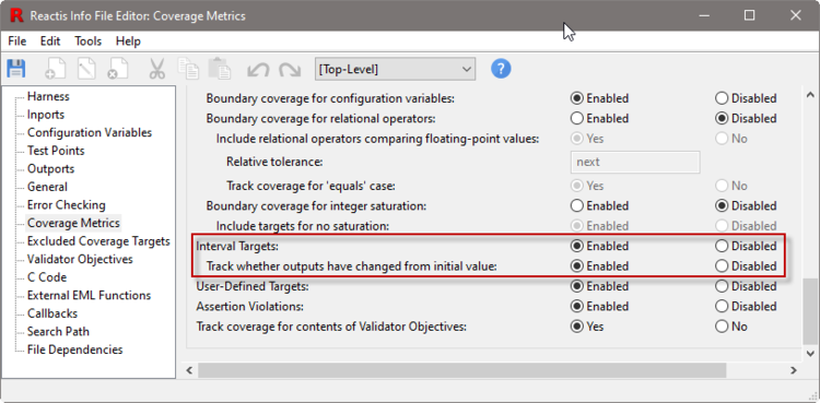
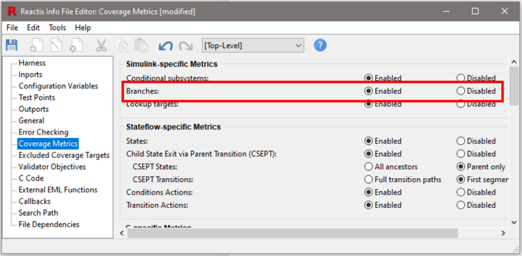
As shown in Figure 6.17, like all metrics,
Interval Coverage can be enabled, disabled, and configured from the
Info File Editor (Edit > Coverage Metrics). When
Track whether outputs have changed from initial value is enabled,
the special interval not initial value (denoted ~y0) is
included in the set of intervals for every outport in a model.
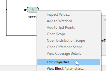
To specify intervals for a harness outport, right-click on the outport and select Edit Properties:
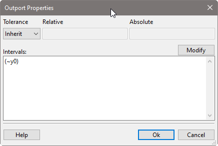
In the resulting Outport Properties dialog, information regarding
Interval Coverage appears below the tolerance information for the outport.
Initially only the built-in interval not initial value (~y0)
is tracked for the outport. Note that the parentheses around the interval
indicate that it is managed automatically and cannot be changed by the
user.
To add intervals, click the Modify button in Outport Properties to open the Modify Outport Intervals dialog:
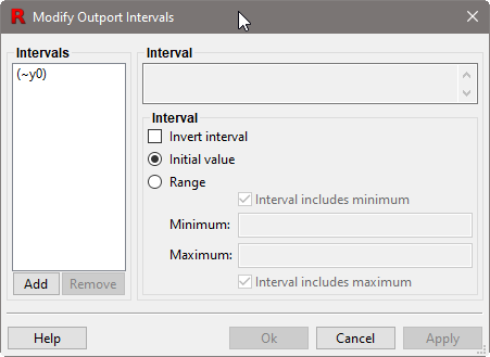
To add the interval 0 to 30 to the tracked intervals, in the dialog:
- Click the Range radio selector,
- Enter 0 for Minimum and 30 for Maximum,
- Click Add
The interval [0:30] now shows up in the list. This interval
will be considered covered if the outport has a value x such that
0 ≤ x ≤ 30.
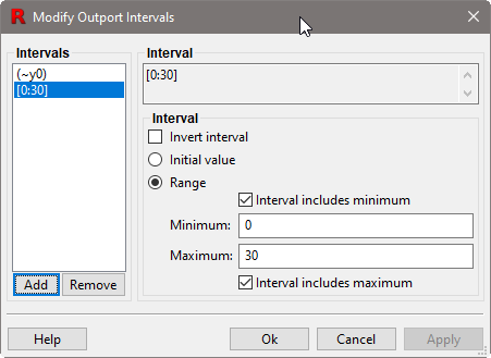
Note that the interval includes the 0 and 30 values. To make the interval
exclude 0, uncheck the box Interval includes minimum, and click
Apply. The interval changes from [0:30] to ]0:30] to
indicate that the interval does not include 0. The maximum value of an
interval can be included and excluded in the same way using the
Interval includes maximum checkbox.
Intervals for test points are manipulated in exactly the same way as outputs using the Test Point Properties dialog.
If an outport or test point has a bus or vector type, then the Modify Intervals dialog will have one or two additional panels to the left: Signals in Bus and Elements of vector. The two panels let you select a single scalar leaf of a composite signal for which to specify a list of intervals. For example, if an outport A is a bus type with elements B and x, B is a bus with elements y and z, and x, y, and z are doubles, then you can specify lists of intervals for each of: A.x, A.B.y, A.B.z.
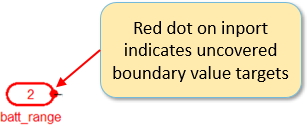
An outport drawn in red with a red dot on its input indicates that the port has at least one uncovered interval target.

A test point symbol drawn in red indicates it has at least one uncovered interval target.

To see the Interval Coverage information, right-click on the outport or test point and select View Coverage Details. A concise summary of the syntax and semantics of the interval coverage metric is given in Table 6.2.
Table 6.2: The syntax and semantics of the interval notation is defined by the following table for an outport or test point X, where Xi denotes the value of X in step i of a test.
Interval X is covered in step i if and only if [min:max]min ≤ Xi ≤ max ]min:max]min < Xi ≤ max [min:max[min ≤ Xi < max ]min:max[min < Xi < max y0Xi is the initial value of X ~intervalinterval is not covered in step i
6.4 Validator-Related Targets
See Chapter 9 for a description of the two Validator-related targets: assertions and user-defined targets.
6.5 Excluding Coverage Targets
Reactis supports three different ways to disable coverage tracking for a subset of targets. When a target is excluded using any of the three mechanisms, Reactis Tester will not try to generate a test to exercise the target and Reactis Simulator will not report the target as uncovered.
6.5.1 Disabling a Coverage Metric
In some cases, tracking a certain metric may not be desirable. For example, if a model contains no lookup tables, you may wish to not use lookup table coverage when working with the model in Reactis. Or, if accomplishing 100% MCC coverage requires an excessive number of tests, you may wish to not track that metric. To help you focus on the set of metrics of highest interest to you, Reactis lets you disable a whole coverage metric.
To disable a coverage metric, do the following:
- make sure Reactis Simulator is disabled
- open the Coverage Metrics tab in the Reactis Info File Editor (select Edit > Coverage Metrics...)
- switch the desired metric to "Disabled"
Disabling a coverage metric will cause it to not be shown in any of the various places where Reactis lists coverage metrics, including the Tester launch and run dialogs, the Coverage Summary dialog, the Coverage Report Browser, and exported coverage reports. Also, Reactis Tester will not target disabled metrics when generating tests.
6.5.2 Excluding a Subsystem
Reactis lets you disable coverage tracking for all targets in a given subsystem of a model. For example, it may not be desirable to track coverage for a referenced model or library system if that portion of your model is being tested by other unit tests.
When Simulator is disabled, you can enable or disable coverage tracking for a subsystem by right-clicking on the subsystem in the Reactis hierarchy panel and selecting the Coverage Tracking entry which has the following sub-menus:
- Enable
- Enable coverage tracking for targets in the subsystem.
- Disable
- Disable coverage tracking for targets in the subsystem.
- Inherit
- The coverage tracking for the subsystem is the same as its parent’s setting.
- Reset to inherited...
- Set the coverage tracking setting for the subsystem and all its descendants to inherited.
- Cumulative
- Enable cumulative coverage tracking for all library subsystem blocks and model references within the selected subsystem. This option is explained in Section 6.6.
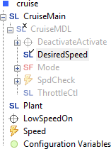
By default, coverage tracking is enabled for the top-level of the model and set to inherit for all other subsystems. As shown in Figure 6.19, visual cues in the hierarchy panel indicate the current coverage tracking setting for each subsystem. An X mark on the icon to the left of a subsystem name indicates that coverage tracking is disabled, whereas a check mark indicates that coverage tracking is enabled. If the icon has neither a check nor an X, then the subsystem is set to inherit its coverage tracking setting. If a subsystem currently has coverage tracking disabled or it inherits a disabled setting, then the subsystem name is grayed out (drawn in a lighter color).
Turning off coverage tracking for a subsystem has the following effects:
- Tester will not attempt to cover targets within the subsystem
- Simulator will not track coverage for targets in the subsystem,
so the targets will not be:
- included in the Coverage Summary dialog,
- included in reports displayed or exported by the Coverage Report Browser,
- highlighted in the main panel
6.5.3 Excluding Individual Targets
Excluding individual targets from coverage tracking allows fine-grained control if a model includes a few specific targets that cannot be exercised. Excluding such targets from coverage tracking (after confirming their unreachable status) can help you achieve the goal of 100% coverage of reachable targets.
Reactis offers two alternative ways to exclude a coverage target. If you simply exclude a target, Reactis will not attempt to exercise the target when generating tests and it will not report it as covered or uncovered. The second way to exclude a target is to exclude and monitor a target. This method lets you assert that a target is unreachable and therefore should not be included in the coverage reports; but, Reactis will also monitor the target and alert you if the target is ever exercised – that is, you will be notified if your claim that the target is unreachable is incorrect. Reactis accomplishes this by automatically creating a Validator assertion for each excluded and monitored target to flag if the target is ever exercised. If such an assertion is violated (either while generating tests in Tester or running the model in Simulator), Reactis will report the violation and Simulator can be employed to investigate how the presumably unreachable target got covered.
All target types tracked by Reactis can be excluded. The method to exclude a target differs slightly by target type.
For decision, condition, MC/DC, MCC, CSEPT, lookup table, input boundary value, and interval targets (see Figure 6.20):
- Right-click on the respective Simulink block, Stateflow transition or C or EML code fragment.
- Select View Coverage Details.
- In the resulting dialog, right-click on the test/step information of the specific target (e.g. "-/-" or "3/17").
- Select the "Track Coverage" menu item.
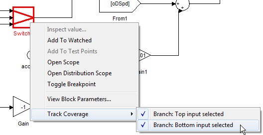
For all other targets right-click on the block, Stateflow transition, or C or EML code fragment, select Track Coverage and select the appropriate target from the sub-menu (see Figure 6.21). A check-mark in the sub-menu listing coverage targets indicates that coverage is currently being tracked for that target.
Selecting Track Coverage brings up the dialog shown in Figure 6.22. This dialog offers three choices for the coverage exclusion status:
- Track coverage for this target
- If this option is selected, coverage is tracked as usual for the target.
- Exclude target from coverage tracking
-
If selected, coverage is not tracked for the target:
- If the target has a specific visual representation (e.g. a branch in a Switch block is represented by a line from an inport to an outport), the visual representation will be drawn in blue (instead of black or red).
- The target’s parent (Simulink block or Stateflow transition) will also be highlighted in blue if all non-excluded targets associated with the block have been covered. As long as any uncovered sub-targets remain, the parent will be highlighted in red.
- The target will not be counted in the coverage summary.
- The target will be added to the list of targets in the Excluded Coverage Targets pane of the Info File Editor (invoked by Edit > Excluded Coverage Targets).
- Whenever the coverage status is displayed for the target (e.g. in coverage reports and when hovering) the status will be "excluded".
- Exclude target from coverage tracking and monitor via assertion
-
The same rules apply as for the case above, with the following additions:
- An assertion will be automatically created for the target. The assertion is included in the "Assertion" count in the coverage summary.
- To indicate the "monitored" status of the target, its status will be shown as "[excluded]" in the coverage report, list of excluded targets and when hovering.
- The associated assertion changes to "violated" status.
- The target and parent block/transition are highlighted in yellow in the main panel.
- In the coverage report, the list of excluded targets, and when hovering the status will be listed as "[t/s]" where t/s is the test/step number in which the target was covered.
- The associated assertion will be listed as violated in the test execution report.
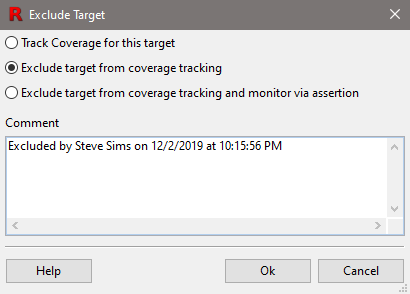
As shown in Figure 6.22, when either Exclude target from coverage tracking or Exclude target from coverage tracking and monitor via assertion is selected, the comment box within the dialog is enabled. The comments are saved in the .rsi file for future reference.
6.6 Cumulative Subsystem Coverage
When a model contains multiple instances of a reference system (either a library subsystem block or model reference), Reactis lets you track coverage cumulatively. Cumulative coverage tracking shares targets between all instances of the same subsystem, which effectively treats the multiple instances as if they were a single instance.
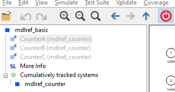
When Simulator is disabled, you can enable cumulative coverage tracking for a subsystem by right-clicking on it in the Reactis hierarchy panel and selecting Coverage Tracking > Cumulative. This will change all library subsystem blocks and model references within the selected subsystem to use cumulative coverage tracking. Cumulatively tracked subsystems are distinguished by a C superimposed on the upper right corner of their icon. A special hierarchy tree node named Cumulatively tracked systems serves as a collection point where all subsystems whose coverage is cumulatively tracked can be inspected. Figure 6.23 shows a hierarchy tree with three subsystems set to use cumulative coverage tracking.
When you right-click on a subsystem and select Coverage Tracking, the Cumulative entry in the sub-menu will be checked if cumulative coverage tracking is turned on. When cumulative coverage tracking is turned on for a subsystem, selecting Coverage Tracking > Cumulative turns it off. Turning off cumulative coverage tracking for a subsystem will cause every instance of the subsystem to be tracked separately. Cumulative coverage for all descendants of a subsystem can be turned off by right-clicking on it and selecting Coverage Tracking > Reset to inherited. Cumulative coverage can also be turned off throughout the entire model by right-clicking on the top node in the hierarchy tree and selecting Coverage Tracking > Enable all.
If a subsystem containing Validator objectives is switched to cumulative coverage then those objectives are no longer tracked because coverage for that instance is no longer tracked individually. Such objectives will be shown grayed-out.
You can add Validator objectives within the cumulative section of the hierarchy tree. Such objectives will then be tracked for all instances of the corresponding system. For assertions, this means that a violation will be registered if an assertion is violated in any instance. User-defined targets will show as covered if they are covered in any instance.
When switching a subsystem to cumulative coverage and at least one instance of that system contains Validator objectives then Reactis will present a warning, allowing you to automatically create copies of those objectives in the cumulative section.
- 1
- Some sets may contain only a single value.
- 2
- Embedded MATLAB coverage tracking becomes enabled when using the Reactis for EML Plugin; otherwise coverage is not tracked in the Embedded MATLAB portions of a model.
- 3
- C code coverage tracking becomes enabled when using the Reactis for C Plugin; otherwise coverage is not tracked in the C code portions of a model.
- 4
- Recall that types are associated with harness inports using the Port Types tab of the Reactis Info File Editor (described in Chapter 5).