Chapter 3 Reactis Model Inspector Top-Level Window
This chapter concentrates on the functionality available in the Reactis Model Inspector top-level window.
3.1 Labeled Window Items
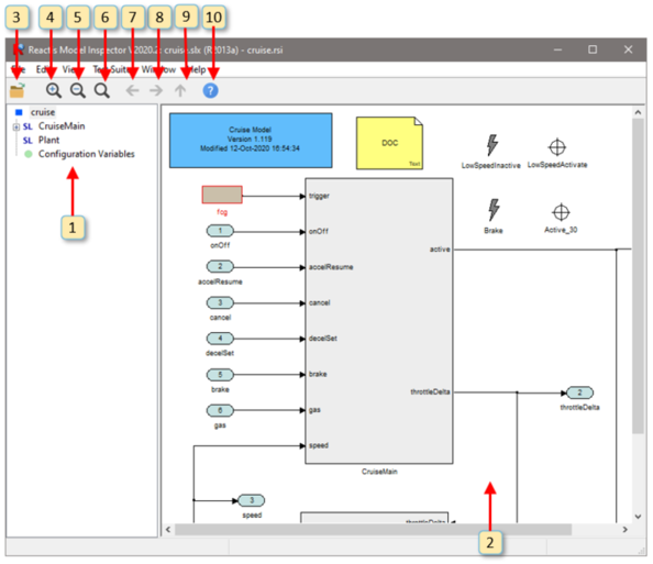
An annotated screen shot of the Reactis Model Inspector top-level window may be found in Figure 3.1. This section describes the functionality of the numbered items in this figure, while the section following discusses the workings of the pull-down menus.
The numbers below refer to the labels in Figure 3.1.
- The model hierarchy panel shows the subsystems in
the model and how they are related. Clicking the + to the
left an item displays the subsystems of the item. Clicking on
an item causes the diagram for the item to be displayed in the
main panel (window item 2). Pressing the
“F2” key causes the parent of the currently displayed system
to be displayed. Hovering in the hierarchy panel over a child
of the currently displayed system causes the child to be
highlighted in the main panel.
Right-clicking on an item in the hierarchy panel causes a pop-up menu to be displayed with an entry Copy System Path. Selecting the entry causes the path of the selected subsystem to be copied to the clipboard. The path can then be easily pasted into another document such as a spreadsheet, text file, or email. The copied system path can also help you easily navigate to the appropriate subsystem in the Simulink editor if you decide to modify a portion of the model currently displayed in Reactis Model Inspector. To do so:
- In the hierarchy panel, right-click on the subsystem of interest and select Copy System Path
- Start MATLAB and open your model in Simulink
- At the MATLAB prompt type
open_system(' - Paste in the system path from the clipboard
- Type
');and hit return - The subsystem of interest will be displayed in the Simulink editor
-
The main panel displays the currently selected Simulink subsystem,
Stateflow diagram, C code, or Embedded MATLAB code. You
may interact with the diagram
in a number of different ways using the mouse including hovering
over model items, double-clicking on items, or right-clicking
in various parts of the panel.
The following mouse operations are available:
- Hovering...
- over a From or Goto block will cause it and its associated block(s) to be highlighted in yellow.
- over a Data Store Read, Data Store Write or Data Store block will cause it and its associated block(s) to be highlighted in yellow.
- over a Validator objective will cause its wiring information to be drawn in blue arrows from the data items monitored (or controlled in the case of a virtual source) to the objective.
- over a top-level input port that is controlled by a virtual source will show a blue arrow indicating the virtual source block that is controlling this input port.
- over a Stateflow transition segment will cause the segment and its label to be highlighted in yellow.
- Clicking...
- on a signal line in a Simulink system highlights the signal in yellow. This makes it easy to trace a signal back to the point where it was generated and forwards to the point where it is consumed (used by a block to compute a new value). The highlighting flows through (backward and forward) the following blocks that do not modify a signal value: Inport, Outport, Subsystem, From, Goto, Data Store Write, Data Store Read.
- in empty space removes signal highlighting.
- Double Clicking...
- on a Simulink block will display the block’s parameters.
- on a Simulink subsystem will cause the subsystem diagram to be displayed in the main panel.
- on a Stateflow state will cause the state’s diagram to be displayed in the main panel.
- on a Simulink S-Function block with an associated Reactis Makefile (.rsm file ) will cause the .rsm file to be displayed in the main panel.
- on a From, Goto or Goto Tag Visibility block will open a dialog listing all matching From and Goto blocks in your model (see Section 3.3).
- on a Data Store Read/Write/Memory block will open a dialog listing all matching blocks in your model (see Section 3.3).
- on a top-level input port will bring up the port type editor (in read-only mode) to inspect the constraint associated with the inport.
- on a configuration variable in the Configuration Variable Panel will bring up a type editor dialog (in read-only mode) to inspect that variable’s type constraint.
- on a Validator expression objective will open the parameter dialog for that objective (in read-only mode).
- Right Clicking...
Causes different pop-up menus to be displayed. The contents of the menu vary based on where the click occurs. A summary of the menu items follows.Right-Click LocationMenu Entries Validator objective (i.e. user-defined target, assertion, or virtual source)- View Properties...
- View properties of the objective.
Simulink block- View Block Parameters...
- Display Simulink block parameters.
Top-level input port or configuration variable in Configuration Variable Panel- View Type...
- Inspect type of top-level input port or configuration variable.
Top-level output port or test point Variable Panel- View Tolerance
- Inspect the tolerance used when comparing the actual value of the top-level output port or test point to its expected value.
When a diagram is too big to display completely in the main panel, scroll bars appear for repositioning the diagram. Alternatively the diagram may be repositioned by left-clicking and dragging in the panel or by using the cursor keys. If your mouse includes a scroll wheel, then you may scroll vertically by clicking in the main panel and then using the scroll wheel.
Left-clicking and dragging in the panel while holding down the control key defines a “print region” that can be used for printing parts of a model. The print region is represented as a shaded blue box; it may be removed using the File -> Remove Print Region menu entry or pressing the escape key.
Finally, pressing the F2 key within this panel causes the parent of the currently displayed subsystem to be displayed, pressing F3 zooms in, and pressing F4 zooms out.
- Load a new model into Reactis Model Inspector.
- Zoom in.
- Zoom out.
- Fit to page.
- Go back in the history of displayed subsystems.
- Go forward in the history of displayed subsystems.
- Display the parent of the currently displayed subsystem.
- Open Reactis Model Inspector help window.
3.2 Menus
This section describes the top-level menu items available in Reactis Model Inspector. Some menu entries also have keyboard shortcuts that enable the relevant operations to be invoked from the keyboard. These shortcuts are displayed to the right of the relevant entries in the menus.
- File menu.
- The file menu contains the following entries.
- Open Model...
- Load a new model into Reactis Model Inspector.
- Close Model.
- Close the currently displayed model.
- Reload Model.
- Reload the currently displayed model.
- Select Info File...
- Specify a Reactis Info File (.rsi file) to be used with the current model. See Chapter 4 for a discussion of editing .rsi files with the Reactis Info File Editor. .rsi files store information that Reactis associates with a model including inport constraints, configuration variable settings, Validator objectives, outport tolerances, and other settings.
- Extract Info File...
- Extract an .rsi file from an .rtp file . Reactis Tester may be configured to store launch parameters and the .rsi file used for a given run in a Reactis Tester Parameter file (.rtp file). Selecting this menu item retrieves the .rsi file from the .rtp file.
- Print...
- Open a print dialog for model printing. Section 3.5 explains this feature in more detail.
- Remove Print Region.
- Clear the selected printing region in the main panel. You may select a region of a model for printing by left-clicking and dragging in the panel while holding down the control key. The resulting selection is highlighted within a blue box. Selecting this menu item removes the blue box.
- Global Settings...
- Opens dialog to adjust Reactis global settings. Section 3.6 describes the use of this dialog.
- Exit Reactis Model Inspector.
- Exit Reactis Model Inspector.
- Edit menu.
-
This menu includes entries used to view .rsi files (open the Reactis Info File Editor in read-only mode) and an entry to launch a model search function. .rsi files contain constraints on the values assumed by top-level inports, details related to Validator objectives, and other model information maintained by Reactis.
- Find...
-
Perform a text search of your model for strings matching a pattern
you specify. Two types of patterns are currently supported. If the
search pattern includes a colon (:), then the text before the colon
corresponds to a Simulink block parameter name and the text after
the colon corresponds to a value for that parameter. For example
the pattern
BlockType:Inportwill initiate a search for all input ports in the model. If the search string contains no colon, then the search will examine Simulink block names, Stateflow state names and actions, Validator objective names, configuration variable names, and C code.The scope of the search (the parts of the model examined for a match) is determined by the subsystem displayed when the search is launched. The scope consists of the currently displayed subsystem and all of its descendants (child subsystems, their children and so forth). Note that the search scope does not change if the search pattern is modified. The scope changes only when the search dialog is dismissed and a new search is launched. To search the entire model select the top-level and launch a search.
The following twelve entries invoke the Info File Editor in read-only mode to the tab specified by the menu entry. - Inport Types...
- Constrain the values generated for top-level inports during test generation.
- Configuration Variables...
- Specify workspace data items that may change in between tests but not during a test.
- Test Points...
- Manipulate test points for observing model behavior. Test points are internal data items that Reactis treats as virtual outputs; specifically, the tool records values for test points in test suites and, when executing a test suite, Reactis Simulator flags any differences between the values computed by a model for a test point and those stored in a test suite.
- Outport Tolerances...
- Specify a tolerance for each outport of a model. When executing a test suite on the model in Reactis Simulator, an outport tolerance specifies the maximum acceptable difference between the value computed by the model for the outport and the value stored in a test suite for the outport.
- General...
- Specify model-specific settings related to how a model executes (e.g. conditional input branch execution and short circuiting).
- Error Checking...
- Specify the set of error checks Reactis will employ (e.g. flagging overflows or NaN values).
- Coverage Metrics...
- Specify the set of coverage metrics to be measured
when working with a model in Reactis. If a metric is disabled:
- the metric will not be targeted by Tester when generating tests, and
- Simulator will not include the targets of the metric in the Coverage Summary dialog, the Coverage Report Browser, and the highlighting in the main panel.
- Excluded Coverage Targets...
- Displays a list of all targets which have been excluded from coverage and allows you to monitor the state or change the coverage tracking setting for each excluded target.
- Validator Objectives...
- Displays a centralized list of all Validator objectives in your model and allows you to monitor, edit, and remove them.
- C Code...
- Displays a list of all locations in your model where C code is used.
- Callbacks...
- Specify fragments of MATLAB code to execute before and/or after a model is loaded. Note that these operations are distinct from the similar Simulink callbacks.
- Search Path...
- Specify model-specific search path.
- Dependencies...
- Specify files on which a model depends.
- View menu.
- The view menu contains the following entries:
- Back.
- Go back in the history of displayed subsystems.
- Forward.
- Go forward in the history of displayed subsystems.
- Go to Parent.
- Cause the parent of the currently displayed subsystem to be displayed in the main panel.
- Zoom In.
- Zoom in the display of the model in the main panel.
- Zoom Out.
- Zoom out the display of the model in the main panel.
- Zoom to Fit.
- Fit to page; same as labeled window item 6.
- Expand Tree.
- Causes the entire tree in the model hierarchy panel to be expanded.
- Collapse Tree.
- Causes the entire tree in the model hierarchy panel to be collapsed.
- Select Label Font...
- Select font for labels in Simulink / Stateflow diagrams.
- Increase Label Font Size...
- Increase size of font for labels in Simulink / Stateflow diagrams.
- Decrease Label Font Size...
- Decrease size of font for labels in Simulink / Stateflow diagrams.
- Select C Source Font...
- Select font for displaying C source code in the main panel when using Reactis for C Plugin.
- Select Line Styles...
- Select styles and colors for drawing various Simulink / Stateflow diagram items.
- Test Suite menu.
- The following menu entry is available:
- Browse...
- Launches the Test-Suite Browser by first opening a file-selection dialog to allow you to indicate which test suite is to be browsed. See Chapter 5 for details.
- Window menu.
- Enables user to switch between different models currently loaded in Reactis Model Inspector.
- Help menu.
-
The Help menu contains the following entries.
- Contents.
- Go to the table of contents in the documentation.
- Index.
- Go to the index in the documentation.
- Frequently Asked Questions.
- Go to the Frequently Asked Questions section of the documentation.
- Release Notes.
- Display the release notes for the current Reactis Model Inspector version.
- Top Level Window.
- Go to the section of the documentation that describes the Reactis Model Inspector top-level window.
- Check for Updates...
- Query the Reactive Systems website to check if a newer version of Reactis Model Inspector is available.
- About.
- Open a dialog displaying the Reactis Model Inspector version and other configuration information. The dialog includes a Copy To Clipboard button to transfer the information to the Windows Clipboard. When requesting assistance, sending this information to Reactive Systems via email often facilitates the efficient delivery of support.
3.3 List of Matching From/Goto or Data Store Blocks
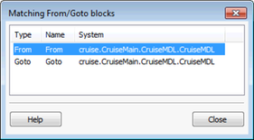
This dialog comes up after double-clicking on a From, Goto, Goto Tag Visibility or Data Store Read/Write/Memory block in Reactis Model Inspector. It lists all other such blocks in your model that match the double-clicked block.
In this dialog you can:
- Double-click on a row to have Reactis highlight the block in the main panel. If the block is located in a different subsystem than the one currently displayed, Reactis will switch to that subsystem.
- Click on a column header to re-sort the table by the values of that column.
- Click on the Close button to close the dialog.
3.4 Configuration Variable Panel
If the model you are inspecting has configuration variables, Reactis Model Inspector will include an entry Configuration Variables in the top-level of the hierarchy panel. Clicking on this entry displays a block in the main panel for each currently defined configuration variable. This panel allows you to view configuration-variable information. Double-clicking on a configuration variable opens the type editor dialog in read-only mode to inspect a constraint for the configuration variable.
3.5 Printing Models
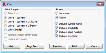
Reactis Model Inspector includes a flexible facility for printing models. Upon selecting menu item File -> Print... the print dialog shown in Figure 3.3 appears. The radio buttons and check-boxes in the Print Range section of the dialog specify which portions of the model should be printed as follows.
- Selection.
- Prints only the portion of the model located within the current print region in the main panel. If no print region is defined, this entry is disabled. A print region is selected by left-clicking and dragging in the main panel while holding down the control key. The print region is cleared by selecting menu item File -> Remove Print Region.
- Current system.
- Prints only the system currently displayed in the main panel.
- Current system and above.
- Prints the system currently displayed in the main panel and all systems between the current system and the top-level system in the current model. Each such system is printed on a separate sheet of paper.
- Current system and below.
- Prints the system currently displayed together with all its subsystems, sub-subsystems, etc. Each system is printed on a separate sheet of paper.
- Whole model.
- Prints the whole model.
- Expand unique library links.
- When checked, library blocks referenced by the model will be printed. Note that each library block is printed only once, even though some blocks might be referenced multiple times by a model.
- Look under masks.
- When checked, masked subsystems will be printed.
The following radio buttons and check-boxes in the Frame section specify whether a frame should be printed on each page, and if so what content should be included in the frame.
- No frame.
- When checked, no frame is printed.
- Frame.
- When checked, a frame is printed.
- Include system name.
- When checked, the name of the system is printed in the upper left part of the page frame.
- Include print date.
- When checked, the date the model was printed is included in the bottom left corner of the frame on each page.
- Include page number
- When checked, the page number is printed in the bottom right corner of the frame on each page.
- Include file name.
- When checked, the name of the .mdl file containing the model and the folder containing the file is printed in the bottom left corner of each page.
The remaining buttons in the print dialog work as follows.
- Help.
- Display print dialog help.
- Page Setup...
- Invokes a dialog that allows the user to specify paper size and margins, and whether printing should be portrait or landscape.
- Preview.
- Open a viewer to display what will be printed.
- Print...
- Begin printing.
- Close.
- Close the dialog (and cancel printing).
3.6 Reactis Global Settings
Selecting File -> Global Settings... invokes the Reactis Model Inspector Global Settings dialog, which allows you to adjust some aspects of the way Reactis Model Inspector operates. The global settings are partitioned into four tabbed panes each described in detail below: General, Path, User Info, and License.
3.6.1 General Settings
The General global settings tab shown in Figure 3.4 includes the following items.
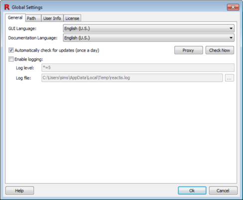
- GUI Language.
- Language used in the Reactis Model Inspector GUI.
- Documentation Language.
- Language used for the in-tool Reactis Model Inspector help.
- Automatically check for updates (once a day).
- Instructs Reactis Model Inspector to check once per day whether updates to Reactis Model Inspector are available for download. If updates are found you will be asked if you would like to download and install the patch. Note: this feature can be disabled at install time; in which case this checkbox will not appear in the dialog.
- Enable logging.
- Enable logging, specify a log level, and indicate the file to which the log should be written. Note that logging degrades performance and can create very large log files; therefore, it is typically only used to diagnose problems. The log level string will be provided by the Reactive Systems support team if you are asked to create a log file.
3.6.2 Path Global Settings
The Path tab of the Global Settings dialog, shown in Figure 3.5, enables you to specify the list of folders in which Reactis Model Inspector will search for files such as Simulink model libraries (.mdl). The order in which folders are listed in the dialog specifies the search order (from top to bottom).
Note that Reactis also gives users the capability to define model-specific search paths which consist of a list of folders to be searched when loading a given model. The model-specific path can be viewed in Reactis Model Inspector by selecting Edit -> Search Path.... When searching for files, the complete search path is constructed by prepending the model-specific path to the global path.
The buttons labeled in the figure work as follows.
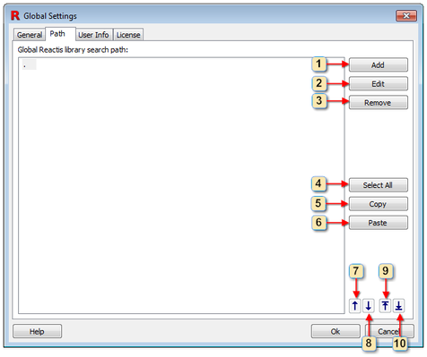
- Add a new folder to the list.
- Open a dialog to edit the currently selected folder.
- Remove the currently selected folder(s) from the list.
- Select all folders in the list.
- Copy the currently selected folder(s) to the clipboard.
- Paste from the clipboard to the list.
- Move the currently selected folder up one spot in the list.
- Move the currently selected folder down one spot in the list.
- Move the currently selected folder to the top of the list.
- Move the currently selected folder to the bottom of the list.
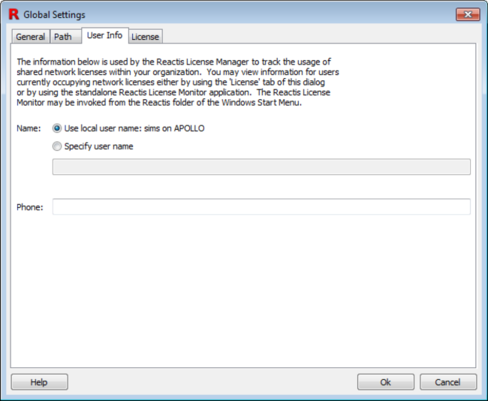
3.6.3 User Info Settings
The User Info settings tab is shown in Figure 3.6. When Reactis Model Inspector is configured to use a remote license server as described in the next section, information contained in this panel is submitted to the server when Reactis Model Inspector is started, and available to all users who have access to the server.
The list of users occupying licenses at a given time may be obtained using the License tab of the Settings dialog as described below, or using the standalone License Monitor utility included in the Reactis Model Inspector distribution. This utility may be invoked by selecting Reactis Model Inspector V2021.2 -> License Manager -> License Monitor from the Windows Start menu.
3.6.4 License Settings
The License tab, shown in Figure 3.7, enables you to query and specify license configuration information. The first two sections display the MAC address of the machine on which Reactis Model Inspector is running and the location of a local license file if one is in use.
The third section of the tab displays a list of servers running the Reactis License Manager. When Reactis Model Inspector is invoked, this list will be searched from top to bottom for an available license. The lowest portion of the tab displays a list of users currently using licenses for the License Manager/product currently selected in the License servers list.
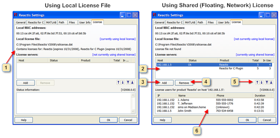
Each of the window items labeled in Figure 3.7 is interpreted and used as follows.
- Information about the contents of the local license file. If there is a problem with the license file, then a description of the error condition is listed here. If no problem exists, then a list of licensed products and their expiration dates is given.
- This is the list of servers running the Reactis License Manager.
Each entry in the list includes the following:
- Host
- The name or IP address of the server running the License Manager.
- Status
- The status of the connection to the License Manager.
- Product
- Name of the product (Reactis, Reactis for C Plugin, Reactis Model Inspector, Reactis for C).
- Total
- The total number of licenses for the product.
- In Use
- The number of currently occupied licenses for the product.
- Add a new License Manager to the list.
- Remove the currently selected License Manager from the list.
- Move the currently selected License Manager up one spot in the list, down one spot in the list, to the top of the list, or to the bottom of the list.
- Information regarding the currently selected License Manager is displayed
here. If there is a problem with the connection to the License Manager,
then a description of the error condition is listed here. If no problem
exists, then for each license currently occupied, this section lists:
- IP Address.
- The IP address of the computer on which the Reactis application occupying the license is running.
- Name.
- The contents of the Name field in the User Info settings tab of the person occupying the license.
- Phone.
- The contents of the Phone field in the User Info settings tab of the person occupying the license.
- Duration.
- The length of the time this computer has been holding the license.