1. Automotive SPICE Overview#
Automotive SPICE, also called ASPICE, offers guidance for organizations conducting automotive engineering projects. Automotive SPICE is based on the ISO/IEC 330xx standards for generic (not industry specific) software development called SPICE (Software Process Improvement and Capability dEtermination). Automotive SPICE defines a process reference model (PRM) that consists of a set of processes for automotive engineering and a process assessment model (PAM) for measuring how well an organization implements the processes of the PRM.
1.1. The Process Reference Model#
The ASPICE process reference model (PRM) includes processes for system engineering, hardware engineering, software engineering, as well as other supporting processes. In this paper we focus on the Software Engineering process group (SWE) shown in Figure 1.1.
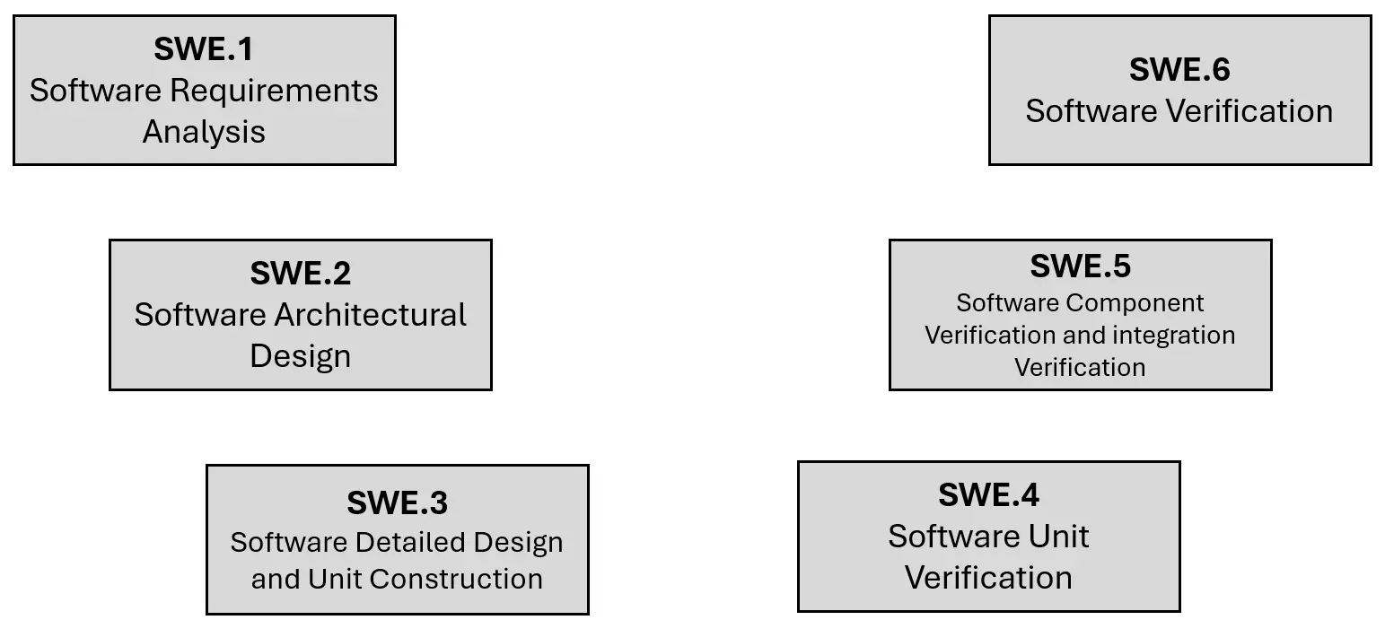
Fig. 1.1 The Software Engineering process group (SWE) consists of six processes aligned according to the well-known V model for software development.#
For each process, the PRM defines a set of base practices (BP) that specify what should be done to achieve the process purpose; however, the PRM does not spell out how to perform the process. The organization selects the techniques and tools to determine how the base practices will be implemented.
1.2. The Process Assessment Model#
The ASPICE process assessment model (PAM) indicates how to determine a capability level from 0 (lowest) to 5 (highest) that an organization achieves when executing a process during a project. Process attributes (PA) lay out what needs to be done to achieve a capability level. Process attributes are assessed to be either not achieved (N), partially achieved (P), largely achieved (L), or fully achieved (F). To achieve capability level i, the process attributes of level i must be largely or fully achieved and all lower levels must be fully achieved. The process attributes for each capability level are shown in Table 1.1. Each process has its own base practices which define the level 1 process attribute, whereas the process attributes for the other levels are generic and apply to all processes.
Level |
Process attributes |
|---|---|
0 : Incomplete |
|
1 : Performed |
Base practices for process performed (PA 1.1) |
2 : Managed |
Performance (PA 2.1) and work products (PA 2.2) managed |
3 : Established |
Processes defined (PA 3.1), processes deployed (PA 3.2) |
4 : Predictable |
Quantitative control (PA 4.1), quantitative analysis (PA 4.2) |
5 : Innovating |
Process innovation (PA 5.1), process innovation implementation (PA 5.2) |
1.3. The Software Engineering Processes#
This section describes the six processes that Automotive SPICE defines in the software engineering process group (SWE). For each process, the standard states the purpose of the process, lays out a set of base practices that should be performed to achieve the purpose, and identifies work products that should be generated during the execution of the process.
1.3.1. Software Requirements Analysis (SWE.1)#
In this process, the software requirements are created, organized, and analyzed. They are based on the system requirements and architecture, or in the case of a software-only product on the stakeholder requirements. The requirements should be verifiable, unambiguous, free of design or implementation details, and consistent (one requirement does not conflict with another).
BP1 |
Specify software requirements |
BP2 |
Structure software requirements |
BP3 |
Analyze software requirements |
BP4 |
Analyze the impact on the operating environment |
BP5 |
Ensure consistency and establish bidirectional traceability |
BP6 |
Communicate agreed software requirements and impact on the operating environment |
1.3.2. Software Architectural Design (SWE.2)#
This process lays out how the static and dynamic aspects of the software architecture should be developed and analyzed. When using model-based design, Simulink models can capture the software architecture. Simulink subsystems, the signals that connect them, and signal types specify the static aspects of the software architecture (how the software is broken down into smaller components and how those components interact). Simulink blocks, Stateflow, Embedded MATLAB can capture the dynamic aspects of the Software architecture.
BP1 |
Specify the static aspects of the software architecture |
BP2 |
Specify the dynamic aspects of the software architecture |
BP3 |
Analyze software architecture |
BP4 |
Ensure consistency and establish bidirectional traceability |
BP5 |
Communicate agreed software architecture |
1.3.3. Software Detailed Design and Unit Construction (SWE.3)#
In this process the software architecture is refined into a detailed design from which software units are produced. In the case of model-based design moving from the architectural model to a detailed design model might entail adding implementation details such as converting floating-point values to fixed-point values. The software units can then be generated from the detailed design model.
BP1 |
Specify the static aspects of the detailed design |
BP2 |
Specify the dynamic aspects of the detailed design |
BP3 |
Develop software units |
BP4 |
Ensure consistency and establish bidirectional traceability |
1.3.4. Software Unit Verification (SWE.4)#
In this process, verification measures are defined and executed to confirm that the software units conform to the behavior laid out in the detailed design. In the case of model-based design, back-to-back testing can be used to check that the software unit conforms to the behavior of the corresponding portion of the detailed design model. Back-to-back testing is performed by giving the same sequence of inputs both the model and the software unit and then comparing the outputs computed by the software against those computed by the model. Verification measures of software quality (independent of conformance to the design) should also be specified and implemented; for example, freedom from run-time errors. A strategy for regression testing should also be defined, including what triggers a regression test (e.g. a change to the design model) and how the regression testing should be performed. For all verification measures it is important to indicate how the results are captured and communicated to relevant stakeholders.
BP1 |
Specify software unit verification measures |
BP2 |
Select software unit verification measures |
BP3 |
Verify software units |
BP4 |
Ensure consistency and establish bidirectional traceability for software unit verification |
BP5 |
Summarize and communicate results |
1.3.5. Software Component Verification and Integration Verification (SWE.5)#
In the nomenclature of Automotive SPICE, a software component is the integration of two or more software units. This process addresses the verification measures that should be defined and applied to software components. For model-based design, many of the verification measures used for unit verification can also be employed for component verification. Back-to-back testing can be performed to check the conformance of a code component to the corresponding model component.
BP1 |
Specify software integration verification measures |
BP2 |
Specify verification measures for verifying software component behavior |
BP3 |
Select verification measures |
BP4 |
Integrate software elements and perform integration verification |
BP5 |
Perform software component verification |
BP6 |
Ensure consistency and establish bidirectional traceability |
BP7 |
Summarize and communicate results |
1.3.6. Software Verification (SWE.6)#
In this process, the fully integrated software is tested, with a focus on checking that the software conforms to the software requirements.
BP1 |
Specify verification measures for software verification |
BP2 |
Select verification measures |
BP3 |
Verify the integrated software |
BP4 |
Ensure consistency and establish bidirectional traceability |
BP5 |
Summarize and communicate results |