3. Reactis Support for Automotive SPICE#
In this section we bring together the prior two sections in order to describe how Reactis can support the software engineering processes of Automotive SPICE.
3.1. Software Requirements Analysis (SWE.1)#
In the Software Requirements Analysis process (SWE.1), BP1 says requirements should be specified and not be ambiguous. BP3 indicates that the requirements should be analyzed. One way to analyze natural language requirements and ensure that they are not ambiguous is to attempt to characterize them using a formal notation. The assertion notations supported by Reactis Validator offer one such path to formalize requirements and thereby realize shortcomings of the natural language version.
For example, consider a requirement that says a cruise control should not activate at a low speed:
If the vehicle speed is less than 25 MPH, then the cruise control shall remain inactive.
This requirement can be formalized with the Reactis Validator assertion below. If the assertion ever evaluates to false, that indicates the requirement has been violated.
!((speed < 25) && active)
But, what if the first draft of this assertion was:
If the vehicle speed is low, then the cruise control shall remain inactive.
If we attempt to create an assertion for this version, it is not possible because the meaning of vehicle speed is low is ambiguous. Realizing the issue, we can refine the natural language requirement so it is verifiable and unambiguous.
Reactis also offers a mechanism to link an assertion to a natural language requirement in order to have bidirectional traceability between the two versions of the requirement.
3.2. Software Architectural Design (SWE.2)#
During the Software Architectural Design process, architectural level Simulink models are drafted to capture the static and dynamic nature of the software architecture. BP3 states that the architecture should be analyzed. As soon as the model simulates, Reactis Tester can be run to search for any runtime errors that could occur during execution as follows:
Load the Simulink model in Reactis.
Select Test Suite > Create….
In launch dialog, click Create Suite button.
When Tester completes, if the Assertion Violations section of the dialog lists any detected violations, then goto step 5; otherwise, goto step 8.
In the results dialog click Load & Close to load the generated test suite into Reactis Simulator.
Use the debug capabilities of Simulator to execute the tests, diagnose the runtime errors, and fix the model to prevent them.
Goto step 2.
If the level of coverage (e.g. 100% MC/DC) is adequate, goto step 9; otherwise, goto step 2, but configure Tester to run longer than in previous run.
Click Load & Close in the Tester results dialog.
Select Simulate > Fast Run with Report… to create a test execution report for the newly created test suite which demonstrates that the model is free of runtime errors and that the tests achieve good coverage. Save the report and and test suite as work products of the process.
Any Reactis Validator assertions created during SWE.1 can be allocated to the appropriate Simulink subsystem during SWE.2 thereby helping to trace back different parts of the architecture (Simulink subsystems) to the software requirements that specify how that component should behave. A requirement is allocated to a subsystem as follows:
Load the model in Reactis.
Navigate in the Reactis GUI to the subsystem containing the signals on which the requirement depends.
Right-click and select Add Assertion > Expression.
Enter the expression that formalizes the requirement, e.g.
!((speed < 25) && active)Map the signals from the model that should be used for the variables in the assertion, e.g. speed and active.
Once assertions are wired into the Simulink architecture model, a search for violations can be launched. Violated assertions can be investigated by executing the resulting tests in Reactis Simulator. The test suite created by Reactis, will also include tests that stress but do not violate assertions. These tests can be viewed as attempts to violate a requirement that did not succeed, i.e. the model behaved properly and satisfied the requirement. So the end result of the iterative process below is a test suite that demonstrates the model satisfies its requirements.
Run Reactis Tester/Validator to search for violations.
If no violations found, then save resulting test suite and goto step 4; otherwise, load the generated test suite in Reactis Simulator in order to investigate violations. Based on the diagnosis fix model (in Simulink).
Goto step 1.
Done.
3.3. Software Detailed Design and Unit Construction (SWE.3)#
In this process, the architectural model is refined into a detailed design model. The design model can then be subjected to the same types of model-in-the-loop testing with Reactis that was described in the previous section for the architectural model:
Reactis Tester can generate tests from the design model in order to check for runtime errors,
Reactis Simulator can produce reports to summarize coverage achieved by a test suite and summarize any runtime errors discovered,
Reactis Validator can check if the design model satisfies the software requirements.
Once the design model has been confirmed to satisfy the software requirements and to meet implicit requirements such as freedom from runtime errors an autocode tool such as Embedded Coder®[1] or TargetLink®[2] generates software units from the detailed design model.
3.4. Software Unit Verification (SWE.4)#
In the Software Unit Verification process, BP1 and BP2 indicate that the verification measures for the software units should be specified and selected, while BP3 says that the selected measures should be executed in order to verify the software units. In model based design, an important verification measure at this stage is to perform back-to-back testing of the C code implementation against the corresponding portion of the design model. Reactis facilitates such back-to-back testing as shown in Figure 1.1 as follows:
Generate a test suite from the verified detailed design model using the Tester component of Reactis for Simulink. Note, that if Reactis was used in SWE.3 (as described in the previous section), then the test suite generated for model-in-the-loop (MIL) testing during SWE.3 can be reused.
Using the Simulator component of Reactis for C, run the tests from step 1 on the C code implementing the software unit.
Any C runtime errors or differences between the outputs computed by the C code and those computed by the model (stored in the test) will be flagged in an HTML report which can also include detailed information about which coverage targets (in the C code) were exercised by the tests.
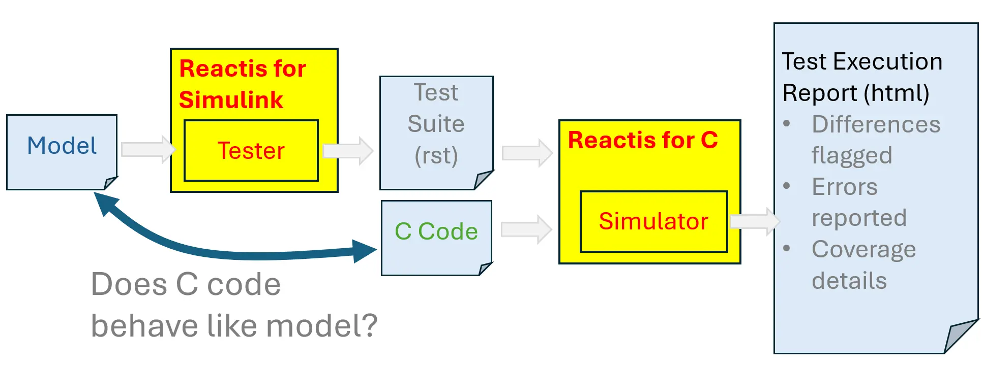
Fig. 3.1 Reactis support for back-to-back testing of C code against a Simulink model.#
Note that if Reactis Validator was used during SWE.3 to check whether the detailed design model satisfies all software requirements allocated to the unit, then when the test suite from that MIL testing is run on the C code, it indirectly confirms that the software unit satisfies the software requirements for the unit.
3.5. Software Component Verification and Integration Verification (SWE.5)#
During SWE.5, two or more software units are integrated to assemble a larger software component. For each software component, there is a corresponding portion of the Simulink model. Reactis supports verification of software components by applying the techniques described for SWE.4, but instead of using them on software units, using them with software components.
3.6. Software Verification (SWE.6)#
During software verification, the fully integrated software is verified against the software requirements. Again Reactis Validator can be used to check that the fully integrated model satisfies all software requirements. The resulting test suite can then be executed on code in order to confirm that the code satisfies all requirements.