4. The Reactis Top-Level Window#
This chapter concentrates on the functionality available in the top-level
window when Simulator is turned off, or disabled. Simulator is always
disabled when the Reactis top-level window first appears. It may also be
explicitly disabled by clicking button  (window
item 12). Clicking button
(window
item 12). Clicking button  (window item 13) turns
Simulator on. The functionality of the Simulator enabled mode is
described in the Reactis Simulator chapter.
(window item 13) turns
Simulator on. The functionality of the Simulator enabled mode is
described in the Reactis Simulator chapter.
4.1. Labeled Window Items#
The items in the Reactis top-level window depend on whether a MATLAB project[1] is loaded.
An annotated screenshot of the window without a loaded project appears in Figure 4.1. When a project is loaded, there are additional items that relate to the project. An annotated screenshot of the window with a loaded project appears in Figure 4.2. This section describes the functionality of the numbered items.

Fig. 4.1 The Reactis top-level window (when no project is loaded).#
The following numbers refer to the labeled window items in Figure 4.1.
The model hierarchy panel shows the subsystems in the model and how they are related. See Model Hierarchy Panel.
The main panel displays the currently selected Simulink subsystem, Stateflow diagram, C code, or Embedded MATLAB code. See Main Panel.
Load a new model into Reactis.
Undo a change to the
.rsifile. Note that.rsifiles contain all information that Reactis associates with a model, so any change to an item manipulated within Reactis (e.g. a top-level constraint, a Validator objective, a comment, etc.) triggers a change to the.rsifile as indicated by a [modified] message in the title bar.Redo last undone change to the
.rsifile.Zoom in.
Zoom out.
Fit to page.
Go back in the history of displayed subsystems.
Go forward in the history of displayed subsystems.
Display the parent of the currently displayed subsystem.
Select harness.
Disable Reactis Simulator.
Enable Reactis Simulator.

Fig. 4.2 The Reactis top-level window when a project is loaded.#
The following numbers refer to the labeled window items in Figure 4.2.
The project hierarchy panel shows the loaded MATLAB project and the referenced project hierarchy. See Project Hierarchy Panel.
The project files panel displays the files of the MATLAB project selected in the project hierarchy panel. See Project Files Panel.
4.3. Model Hierarchy Panel#
The model hierarchy panel (Figure 4.1 item 1) shows the subsystems in the model and how they are related. Clicking on a + to the left of an item displays the subsystems of the item, while clicking on a - to the left of an item hides the subsystems. Clicking on the name or icon of an item causes the diagram for the item to be displayed in the main panel (Figure 4.1 item 2). Pressing the “F2” key causes the parent of the currently displayed system to be displayed. Hovering in the hierarchy panel over a child of the currently displayed system causes the child to be highlighted in the main panel.
Right-clicking on an item in the hierarchy panel causes a pop-up menu to be displayed with four enabled entries, Coverage Tracking, Create New Harness…, Copy System Path, and Open in Simuilink with several disabled entries. The disabled menu items become enabled when Simulator is enabled and are described in the Reactis Simulator chapter.
The Coverage Tracking entry lets you modify how coverage is tracked for the given subsystem. Coverage for a subsystem can either be tracked cumulatively, or disabled altogether. If you disable coverage tracking for a subsystem, Reactis Tester will not attempt to exercise targets within the subsystem when generating tests and Simulator will not display coverage information for targets in the subsystem. See Excluding a Subsystem for details on disabling coverage tracking. See Cumulative Subsystem Coverage for details on cumulative coverage tracking.
The Create New Harness… entry creates a new test harness for the subsystem in order to test it in isolation (see Test Harness Pane).
The Copy System Path entry causes the path of the selected subsystem to
be copied to the clipboard. The pasted text is a suitable argument to the
MATLAB open_system command, although the Open in Simulink menu item
offers a more direct way to navigate from a subsystem in the Reactis hierarchy
panel to the subsystem in the Simulink editor. The pasted text can be
used with open_system as follows:
In the hierarchy panel, right-click on the subsystem of interest and select Copy System Path
Start MATLAB and open your model in Simulink
At the MATLAB prompt type
open_system('Paste in the system path from the clipboard
Type
')to complete the command. At this point, the command you entered should look something like this:open_system('adaptive_cruise/Controller/ACC Override')Hit Enter. The subsystem of interest will be displayed in the Simulink editor.
The Open in Simulink entry allows you to open the item that is clicked in Simulink. See Open Current Model in Simulink for more details.
4.4. Project Hierarchy Panel#
The project hierarchy panel (Figure 4.2 item 15) is shown if (and only if) a MATLAB project is loaded. The panel contains a tree showing the project reference relationships, with the loaded project at the root of the tree. Clicking on a project causes it to be selected. The files of the selected project are shown in the Project Files Panel. More information about a project in the tree can be viewed in the Project Viewer Window which is opened by right-clicking (anywhere in the Project Hierarchy Panel) and selecting View Project Properties. A project in the tree can be opened in its own Reactis window by right-clicking on its name and selecting Open Project from the pop-up menu.
4.5. Project Files Panel#
The project files panel (Figure 4.2 item 16) shows the files in the definition
of the MATLAB project currently selected in the Project Hierarchy
Panel. Double-clicking on an .slx file opens the
model in Reactis with respect to the current project (the project’s path and
initialization files will be used when processing the model). A model can also
be opened by right-clicking on its file and selecting Open Model from the
pop-up menu. If there is already another model open in the Reactis window, the
model opens in a new Reactis window with the current project.
4.6. Reactis Main Panel#
The main panel (Figure 4.1 item 2) displays the Simulink subsystem or Stateflow diagram currently selected in the Model Hierarchy Panel. C code or EML code may also be displayed in the main panel if you are using Reactis for C Plugin or the Reactis for EML Plugin. You can use the mouse to interact with the diagram in a number of different ways, including hovering over model items, single- or double-clicking on items, and right-clicking in various parts of the panel. Note that some operations in the main panel are only available when Simulator is enabled. See the Reactis Simulator chapter for a description of those operations. The following sections describe mouse operations available when Simulator is disabled.
4.6.1. Hovering#
Hover Location |
Hover Effect |
|---|---|
From or Goto block |
Highlights block and its associated block(s) in yellow. |
Data Store Read, Data Store Write or Data Store block |
Highlights block and its associated block(s) in yellow. |
Validator objective |
Draws objective’s wiring information in blue arrows from the data items monitored to the objective. |
Top-level input port that is controlled by a virtual source (see Virtual Sources) |
Draws blue arrow indicating the virtual source block that is controlling this input port. |
Any block or port |
Displays block name and a brief description. |
Stateflow transition segment |
Highlights the segment and its label in yellow. |
Contents of the comment |
4.6.2. Clicking#
Click Location |
Click Effect |
|---|---|
Signal line |
Highlights the signal in yellow. This makes it easy to trace a signal back to the point where it was generated and forwards to the point where it is consumed (i.e., the signal enters a block which uses it to compute a new value). The highlighting flows through (backward and forward) the following blocks which do not modify the signal’s value: Inport, Outport, Subsystem, From, Goto, Data Store Write, Data Store Read, Bus Creator, Bus Selector. |
Empty space |
Removes signal highlighting. |
Validator objective |
Select the objective for subsequent resizing |
Select the comment for subsequent resizing |
4.6.3. Double-Clicking#
Double-Click Location |
Double-Click Effect |
|---|---|
Simulink block |
Displays the block’s parameters. |
Simulink subsystem |
Displays the subsystem diagram in the main panel. |
Stateflow state |
Displays the state’s diagram in the main panel. |
Simulink S-Function block with an associated |
Displays the |
From, Goto or Goto Tag Visibility block |
Opens a dialog listing all matching From and Goto blocks in your model (see Lists of Matching From/Goto or Data Store Blocks). |
Data Store Read/Write/Memory block |
Opens a dialog listing all matching blocks in your model (see Lists of Matching From/Goto or Data Store Blocks). |
Harness input port |
Opens type editor dialog to modify the port’s type (see Type Editor Dialog). |
Configuration variable in the Configuration Variable Panel |
Opens type editor dialog to modify the variable’s type. |
Validator expression objective |
Opens the parameter dialog for that objective. |
Open the Comment Editor to view or modify the comment. |
4.6.4. Right-Clicking#
Causes different pop-up menus to be displayed. The contents of the menu vary based on where the click occurs and whether or not Simulator is enabled. A summary of the menu items available when Simulator is disabled follows. For descriptions of the menu entries available when Simulator is enabled, see the Labeled Window Items section.
Right-Click Location |
Menu Entries (when Simulator is disabled) |
|---|---|
Simulink signals, Simulink blocks, Stateflow variables |
|
White space in Stateflow state or Simulink subsystem |
|
White space at top-level of model |
|
Validator objective (i.e. user-defined target, assertion, or virtual source) |
|
Simulink top-level input port that is wired to virtual source |
|
Simulink S-Function block |
These items are visible only if Enable white-box analysis of C code is enabled in the Reactis for C pane of the Reactis Global Settings dialog. Note that you will need a license for the Reactis for C Plugin in order to use this functionality.
|
Simulink block |
|
Harness input port or configuration variable in Configuration Variable Panel |
|
Simulink subsystem or Stateflow diagram |
|
Model Reference block |
|
|
4.6.5. Dragging the Mouse#
When a diagram is too big to display completely in the main panel, scroll bars appear for repositioning the diagram. Alternatively the diagram may be repositioned by left-clicking and dragging in the panel or by using the cursor keys. If your mouse includes a scroll wheel, then you may scroll vertically by clicking in the main panel and then using the scroll wheel.
Left-clicking and dragging in the panel while holding down the control key causes the display to zoom so that the contents of the selected area are magnified.
4.6.6. Keyboard Shortcuts#
Finally, pressing the F2 key within this panel causes the parent of the currently displayed subsystem to be displayed, pressing F3 zooms in, and pressing F4 zooms out.
4.7. Lists of Matching From/Goto or Data Store Blocks#
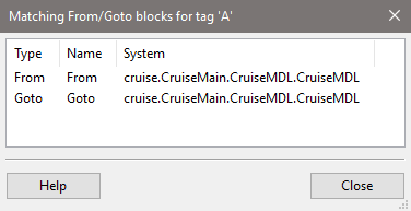
Fig. 4.3 The list of matching From/Goto or Data Store blocks.#
This dialog opens after double-clicking on a From, Goto, Goto Tag Visibility or Data Store Read/Write/Memory block in Reactis. It lists all other such blocks in your model that match the double-clicked block.
In this dialog you can:
Double-click on a row to have Reactis highlight the block in the main panel. If the block is located in a different subsystem than the one currently displayed, Reactis will switch to that subsystem.
Click on a column header to re-sort the table by the values of that column.
Click on the Close button to close the dialog.
4.8. Configuration Variable Panel#
If you have defined configuration variables for your model (see Configuration Variables Pane), Reactis will include an entry Configuration Variables in the top-level of the hierarchy panel. Clicking on this entry displays a list in the main panel containing and entry for each currently defined configuration variable. This panel allows you to view and manipulate configuration-variable information.
Double-clicking on a configuration variable when Simulator is disabled opens the type editor dialog to specify a constraint for the configuration variable. When Simulator is enabled and at the start of a simulation run (no steps have been taken), double-clicking on the configuration variable opens a dialog to specify a value for the variable.
When Coverage > Show Details is selected in Simulator, information on boundary value coverage for configuration variables is conveyed in the panel. A block is highlighted in red if it has any uncovered boundary value targets. See Boundary Values for Inports, Test Points, and Configuration Variables for a description of the boundary value targets associated with a configuration variable. Hovering over the variable in this panel when Simulator is enabled displays test and step in which exercised targets were covered.
4.9. Extracting Subsystems#
Note
The Test Harness mechanism now supported by Reactis is usually the easier and more robust way to achieve what was previously done with Extract Subsystem.
It is sometimes useful to apply Reactis to individual subsystems within a
larger model. For example, if a given model is closed-loop, with a
controller connected to a plant, then isolating the controller subsystem
may be needed in order to generate tests for the controller. In other
cases, very large models might require subsystem-at-a-time
analysis. Reactis enables such analysis by providing a facility to extract
subsystems from models. This feature isolates a subsystem, optionally along
with portions of the model involved in triggering the subsystem, and stores
the result as a new model in a separate .slx file.
When extracting a subsystem, Reactis retains the hierarchical structure of the original model. That is, the original subsystem interfaces enclosing the extracted subsystem are retained, although the input and output ports connected to these interfaces are altered to coincide with those of the extracted subsystems. Retaining the model hierarchy in this fashion facilitates the inclusion of triggering mechanisms and Data Store Memory blocks in the extracted model.
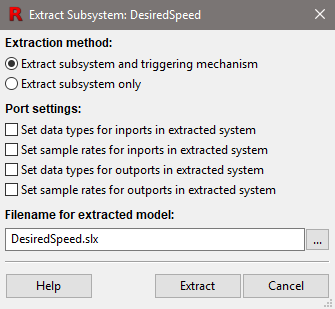
Fig. 4.4 The Extract Subsystem dialog.#
The subsystem extraction utility is invoked by loading a model into Reactis, then right-clicking on the Simulink subsystem or Stateflow chart to be extracted and selecting the Extract Subsystem entry in the pop-up menu. This causes the Extract Subsystem dialog shown in Figure 4.4 to appear. Using the dialog you can specify the name of the file in which to store the extracted model and whether the triggering mechanism should be included.
The Port settings section lets you specify if information (type and sample rate) from the original model should be propagated to the top-level ports of the extracted subsystem. Note that when this information is not propagated, the types and sample rates inferred for the ports of the extracted subsystem may differ from those inferred in the original model (since type and sample rate information has been removed in the extracted model). When the propagation is enabled, for each port P of the subsystem being extracted, the extraction routine:
Traces the signal connected to P up one level in the hierarchy to a port P’
Records the type/rate inferred for P’ in the original model
Explicitly sets the type/rate for P’ in the extracted model
The following limitations apply:
If the type of P’ is a virtual bus then the type will not propagate.
If P’ has multiple sample rates or is triggered by an irregular mechanism such as a Stateflow chart then the sample rate will not propagate.
When you click Extract, Reactis will extract the subsystem, save it under
its new name, open a new Reactis window, and load the extracted model. Note
that the extracted subsystem is saved as a standard .slx file, making it
easy to edit the extracted model using Simulink if changes to new model are
necessary.
If you select Extract subsystem and triggering mechanism then portions of the original model outside the subsystem of interest, but involved in the triggering of that subsystem will be included in the extracted model. More precisely, if the extracted subsystem
is a triggered subsystem,
is located within a triggered subsystem, or
contains one or more triggered subsystems whose triggers are connected to something outside the extracted subsystem
then Reactis determines which portions of the model residing outside of the extracted subsystem should be retained in order to trigger the extracted subsystem properly. This ensures that the simulation times during which the extracted subsystem is executed match those of the subsystem before it was extracted.
If the extracted subsystem references Data Store Memory blocks located outside the extracted subsystem, Reactis will keep those Data Store Memory blocks. However, Reactis will not keep any Data Store Write blocks outside the extracted subsystem.
Note that the extraction tool can extract parts of a model even if Reactis reports errors when trying to run it. This enables Reactis to be used on models that contain Simulink features that are unsupported by Reactis, as long as those features are not used in the extracted subsystem. For example, one may extract a discrete-time controller subsystem from a model that includes a continuous-time plant.
4.10. Unpacking Top-Level Buses#
If a model has bus inputs at the top level, this feature lets you generate a wrapper model that has no bus inputs, but has scalar inputs that feed into Bus Creator blocks that construct buses suitable for input to the original model which is referenced by a Model Reference block. The operation can be invoked by right-clicking in white space at the top level of the model and selecting Unpack Bus Inports to open the dialog shown in Figure 4.5. The generated wrapper model will be stored in a new .slx file named in the entry box of the dialog. Two checkboxes let you configure how the wrapper model is generated:
- Stub unused elements in top-level inport buses
When checked, if an element of a bus is unused, no input port will be created for that element. Instead, the signal for that element will be connected to a Ground block.
- Hide stubbed elements in wrapper subsystem
When checked, create a wrapper subsystem around the Inport/Ground blocks so that the top-level system looks cleaner (since it contains only the scalar input ports and not the stubbed signals).
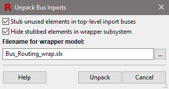
Fig. 4.5 The dialog to unpack top-level buses into scalar inputs.#
4.11. Printing Models#
Reactis includes a facility for printing models. The print dialog shown in Figure 4.6 appears when you select File > Print….
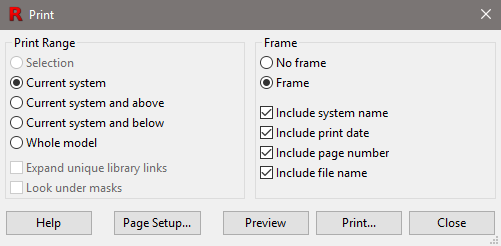
Fig. 4.6 The Print dialog.#
The radio buttons and check-boxes in the Print Range section of the dialog specify which portions of the model should be printed as follows.
- Selection.
Prints only the portion of the model located within the current print region in the main panel. If no print region is defined, this entry is disabled. A print region is selected by left-clicking and dragging in the main panel while holding down the control key. The print region is cleared by selecting menu item File > Remove Print Region.
- Current system.
Prints only the system currently displayed in the main panel.
- Current system and above.
Prints the system currently displayed in the main panel and all systems between the current system and the top-level system of the model. Each such system is printed on a separate sheet of paper.
- Current system and below.
Prints the system currently displayed together with all its subsystems, sub-subsystems, etc. Each system is printed on a separate sheet of paper.
- Whole model.
Prints the whole model.
- Expand unique library links.
When checked, library blocks referenced by the model will be printed. Note that each library block is printed only once, even though some blocks might be referenced multiple times by a model.
- Look under masks.
When checked, masked subsystems will be printed.
The following radio buttons and check-boxes in the Frame section specify whether a frame should be printed on each page, and if so what content should be included in the frame.
- No frame.
When selected, no frame is printed.
- Frame.
When selected, a frame is printed.
- Include system name.
When checked, the name of the system is printed in the upper left part of the page frame.
- Include print date.
When checked, the date the model was printed is included in the bottom left corner of the frame on each page.
- Include page number
When checked, the page number is printed in the bottom right corner of the frame on each page.
- Include file name.
When checked, the name of the .slx file containing the model and the folder containing the file is printed in the bottom left corner of each page.
The remaining buttons in the print dialog work as follows.
- Help.
Display print dialog help.
- Page Setup…
Invokes a dialog that allows the user to specify paper size and margins, and whether printing should be portrait or landscape.
- Preview.
Open a viewer to display what will be printed.
- Print…
Begin printing.
- Close.
Close the dialog (and cancel printing).
4.12. Reactis Global Settings#
Selecting File > Global Settings… invokes the Reactis Global Settings dialog, which allows you to adjust the behavior of Reactis. The global settings are partitioned into seven tabbed panes each described in detail below: General, Reactis for C, Reactis for EML, MATLAB, Path, Files, User Info, and License.
4.12.1. General Global Settings#
The General global settings pane shown in Figure 4.7 includes the following items.
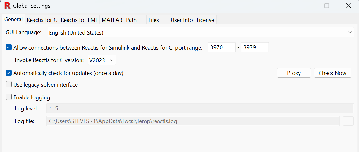
Fig. 4.7 The Global Settings dialog with the General pane selected.#
- GUI Language.
Language used in the Reactis GUI.
- Allow connections between Reactis and Reactis for C.
If enabled, Reactis will a. listen for and respond to incoming link connections from Reactis for C and b. Show the File > Invoke Reactis for C menu item to start and link to Reactis for C. See the Linking with Reactis for C chapter for more information on this functionality.
- Invoke Reactis for C version.
This drop-down box lists installed versions of Reactis for C that support linking. The selected version will be invoked when the user selects File > Invoke Reactis for C. See the Invoking Reactis for C from Reactis for Simulink section for more information.
- Automatically check for updates (once a day).
Instructs Reactis to check once per day whether updates to Reactis are available for download. If updates are found you will be asked if you would like to download and install the patch. Note: this feature can be disabled at install time; in which case this checkbox will not appear in the dialog.
- Use legacy solver interface
V2024 introduced a new framework for interfacing with SMT solvers to flag unreachable code and select test steps that exercise new coverage targets.
If there is an issue with the new framework, you may revert to the legacy interface by checking this box.- Enable logging.
Enable logging, specify a log level, and indicate the file to which the log should be written. Note that logging degrades performance and can create very large log files; therefore, it is typically only used to diagnose problems. The log level string will be provided by the Reactis support team if you are asked to create a log file.
4.12.2. Reactis for C Global Settings#
This pane is used to enable and configure the Reactis for C Plugin.
4.12.3. Reactis for EML Global Settings#
This pane is used to enable and configure the Reactis for EML Plugin.
4.12.4. MATLAB Global Settings#
Reactis invokes MATLAB when importing a model for simulation, test-generation, and validation. The MATLAB global settings pane, shown in Figure 4.8, enables you to configure some aspects of how Reactis invokes MATLAB.
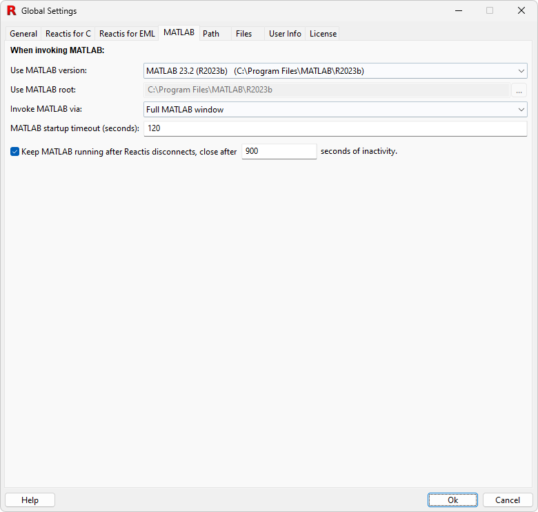
Fig. 4.8 The Global Settings dialog with the MATLAB pane selected.#
- Use MATLAB version.
If you have multiple versions of MATLAB installed, this pull-down menu may be used to specify the version of MATLAB that Reactis will invoke. Each installation of MATLAB that Reactis automatically detects will have an entry in the menu. The menu includes two additional entries:
- None specified (use Windows path)
When this entry is selected, Reactis will invoke the version of MATLAB that appears first in the Windows path.
- Custom
When this entry is selected, Reactis will invoke the version of MATLAB that appears in the MATLAB root text entry box (just below this menu in the MATLAB pane of the global settings dialog).
- Use MATLAB root.
This text entry box becomes enabled when the Custom entry of the MATLAB version menu is selected. By entering a folder name (directly or by clicking the button to the right and using the file-selection dialog), you specify a folder containing the MATLAB installation which Reactis should use. This configuration is typically only used for a custom MATLAB installation that Reactis is unable to detect automatically.
- Invoke MATLAB via:
MATLAB supports several different mechanisms for third party applications to invoke it. Each method has advantages and disadvantages. This menu lets you configure which mechanism will be used by Reactis to invoke MATLAB. The options are:
- MATLAB engine interface via C API
This option works with older versions of MATLAB, but requires administrator privileges to switch between MATLAB versions.
- Windows COM interface
This option does not require administrator privileges to switch between MATLAB versions, but: does not work with R2006b or earlier, is partially compatible with R2007b through R2011b (you can switch between only one MATLAB installation in this range and newer versions), is fully compatible with R2012a and later.
- Full MATLAB window
This option will start a full MATLAB session to communicate with. It is a useful option if other methods of invoking MATLAB fail but will require more time for MATLAB to start up.
- Full MATLAB window (hidden)
Similar to the previous option but hides the MATLAB window it is communicating with. This is less distracting but for some models MATLAB will not work properly if the window is hidden.
- MATLAB start up timeout (seconds).
When Reactis invokes MATLAB, it will wait this long for a response indicating a successful invocation before assuming that MATLAB will not start properly. This setting is unavailable when using the Windows COM interface.
- Keep MATLAB running after Reactis disconnects.
When Reactis invokes MATLAB, it will use this option to determine whether to leave the MATLAB instance running so that there is no need to wait for a new MATLAB session to start when Reactis uses MATLAB subsequently. This is useful in certain scenarios, for example, when using Reactis on a model while making frequent changes to the model in Simulink, or running Reactis on a large number of models either in the GUI or via the API. The MATLAB instance that is left running will close itself if Reactis has not used it for a period of time. This timeout period is specified in seconds. The option to leave the MATLAB instance running is not available if MATLAB is invoked via “MATLAB engine interface via C API” or “Windows COM interface”. In those cases Reactis always closes the MATLAB instance after it has been used.
4.12.5. Path Global Settings#
The Path pane of the Global Settings dialog, shown in
Figure 4.9, enables you to specify
the list of folders in which
Reactis will search for files such as Simulink model libraries (.slx),
MATLAB scripts (.m), and S-Functions (.dll, .mexw32, .m). The order in
which folders are listed in the dialog specifies the search order (from top
to bottom).
Note
Reactis uses other paths when searching for files. The complete search path is constructed by concatenating:
the model-specific search path, which is specific to the loaded model,
the project search path, if a project is loaded, and
the global search path, described here,
in the order specified above. The model-specific path is set using the Reactis Info File Editor. The project search path can be viewed in the Project Viewer Window.
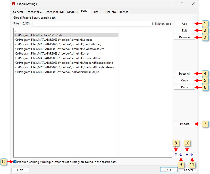
Fig. 4.9 The Global Settings dialog with the Path pane selected.#
The buttons labeled in the figure work as follows.
Add a new folder to the list.
Open a dialog to edit the currently selected folder.
Remove the currently selected folder(s) from the list.
Select all folders in the list.
Copy the currently selected folder(s) to the clipboard.
Paste from the clipboard to the list.
Invoke MATLAB, query the MATLAB path, and add each folder in the MATLAB path to the list.
Move the currently selected folder up one spot in the list.
Move the currently selected folder down one spot in the list.
Move the currently selected folder to the top of the list.
Move the currently selected folder to the bottom of the list.
Produce warning if multiple instances of a library are found in the search path.
4.12.6. Files Global Settings#
The Files pane, shown in Figure 4.10, lets
you specify the folder where Reactis should store files that it
creates. These files include Reactis Info (.rsi), Reactis Profile
(.rsp), and Reactis Cache (.mwi) files. The setting also determines the
default location (which you can override) for Reactis test suite (.rst)
and coverage report (.html) files.
If you choose to specify a subfolder, then the folder name entered in the
textbox is relative to the model folder. The special string %MODELNAME%
may be included in the subfolder name and will be replaced by the base name
of the model file.
For example, for a model cruise.slx located in a folder c:\models, a
subfolder string of reactis\%MODELNAME% will cause the files associated
with cruise.slx to be stored in
c:\models\reactis\cruise.
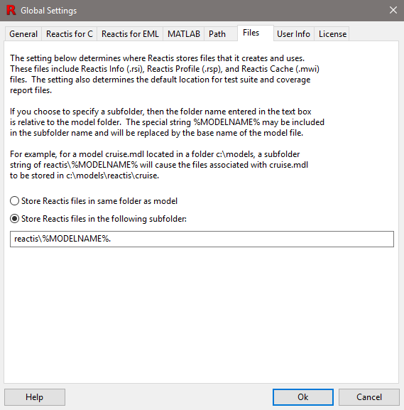
Fig. 4.10 The Files pane of the Global Settings dialog lets you specify the folder where Reactis should store any files that it creates.#
4.12.7. User Info Global Settings#
The User Info pane is shown in Figure 4.11. When Reactis is configured to use a remote license server as described in the next section, information contained in this panel is submitted to the server when Reactis is started, and available to all users who have access to the server.
The list of users occupying licenses at a given time may be obtained using the License pane of the Global Settings dialog as described below, or using the standalone License Monitor utility included in the Reactis License Manager distribution. This utility may be invoked from the Windows Start menu.
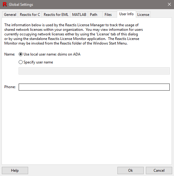
Fig. 4.11 The Global Settings dialog with the User Info pane selected.#
4.12.8. License Global Settings#
The License pane, shown in Figure 4.12, enables you to query and specify license configuration information. The first two sections display the MAC address of the machine on which Reactis is running and the location of a local license file if one is in use.
The third section of the pane displays a list of servers running the Reactis License Manager. When Reactis is invoked, this list will be searched from top to bottom for an available license. The lowest portion of the pane displays a list of users currently using licenses for the License Manager/product currently selected in the License servers list.
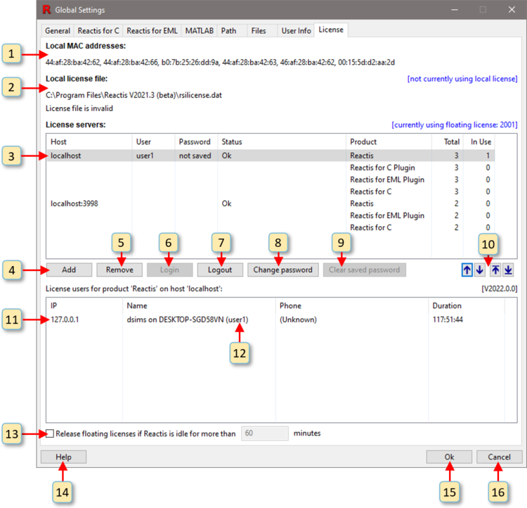
Fig. 4.12 The Global Settings dialog with the License pane selected.#
Each of the window items labeled in Figure 4.12 is interpreted and used as follows.
The MAC address of the computer on which the Reactis is running.
Information about the contents of the local license file. If there is a problem with the license file, then a description of the error condition is listed here. If no problem exists, then a list of licensed products and their expiration dates is given.
The list of servers running the Reactis License Manager. Each entry in the list includes the following:
- Host
The name or IP address of the server running the License Manager.
If access control is enabled by a Reactis License Manager, then users must provide a username and password to authenticate and request a license.
- User
Username of the person requesting a license.
- Password
Password for the person requesting a license.
- Status
The status of the connection to the License Manager.
For each product managed by the server:
- Product
Name of the product (Reactis, Reactis for C Plugin, Reactis Model Inspector, Reactis for C).
- Total
The total number of licenses for the product.
- In Use
The number of currently occupied licenses for the product.
Add a new License Manager to the list.
Remove the currently selected License Manager from the list.
Log in to the License Manager.
Log out of the License Manager.
Change the password of the current user that is logged in.
Clear the saved password for the current user, requiring the user to enter password on next attempt to login.
Move the currently selected License Manager up one spot in the list, down one spot in the list, to the top of the list, or to the bottom of the list. These buttons are only enabled when the list contains more than one License Manager.
Information regarding the currently selected License Manager is displayed here. If there is a problem with the connection to the License Manager, then a description of the error condition is listed here. If no problem exists, then for each license currently occupied, this section lists:
- IP Address.
The IP address of the computer on which the Reactis application occupying the license is running.
- Name.
The contents of the Name field in the User Info pane of the person occupying the license.
- Phone.
The contents of the Phone field in the User Info pane of the person occupying the license.
- Duration.
The length of the time this computer has been holding the license.
The username for the user that is logged in.
Check box to activate the release of a floating license that is idle for a predetermined number of minutes.
View the Reactis License Manager documentation.
Close the window and save changes made to the list of monitored servers.
Close the window without saving any changes made to the list of monitored servers.
4.13. Default Model-Specific Settings#
The Default Model-Specific Settings dialog lets you specify default
settings to be used when creating a new .rsi file. Whenever a new .rsi
file is created, these settings are used in the new .rsi
file. Subsequently, the settings for the model are modified using the Info
File Editor. The dialog includes the following panes:
- General
Various settings primarily related to how a model executes (e.g. conditional input branch execution, short circuiting, etc.)
- Error Checking
What types of errors should be flagged (overflows, NaN values, etc.)
- Coverage Metrics
Settings that specify which coverage metrics are used for a model and how the coverage metrics are configured (e.g. multi-block versus traditional MC/DC).
- C Code
Settings to configure the Reactis for C Plugin.
- Requirement Link Patterns
Patterns which are used to create requirement links (see Linking to Requirements Documents).
The Reactis Info File editor includes a pane corresponding to each of the above five panes. For a description of each setting see the Reactis Info File Editor chapter.
4.14. Open Current Model in Simulink#
When working with a model in Reactis, you can right-click in various locations and select a menu item in order to cause Reactis to start Simulink, load the model in Simulink, and navigate to a particular location within the model. This operation is available when you right-click on an item in the hierarchy panel as well as when you right-click in the main Reactis panel in empty space or on a subsystem, block, state, or transition.
4.14.1. Open in Simulink#
The Open in Simulink menu item is available when you right-click in the hierarchy panel on a Simulink subsystem (SL), Stateflow chart (SF) or MATLAB Function (ML). When you select the menu entry, the current model is loaded in Simulink and the item you right-clicked on is displayed in the Simulink editor.
Right-clicking within empty space in the Reactis main panel also provides the menu option Open in Simulink that opens the contents of the Reactis main panel in Simulink.
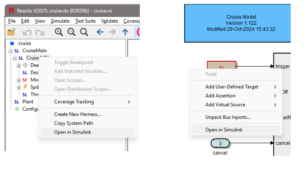
Fig. 4.13 The left image shows the Open in Simulink option when right-clicking in the hierarchy panel. The right image shows the Open in Simulink option when right-clicking in empty space in the Reactis main panel. Selecting either one causes the current model to be loaded in Simulink and the right-clicked item to be displayed when Simulink opens.#
4.14.2. Highlight in Simulink#
To highlight a specific item (block, state, or transition) in Simulink, right-click on the item in the Reactis main panel and select menu option Highlight in Simulink. This will load the model in Simulink, open it to the system containing the right-clicked item, and highlight the item (Simulink block, state, or transition will be highlighted by standard Simulink highlighting conventions).
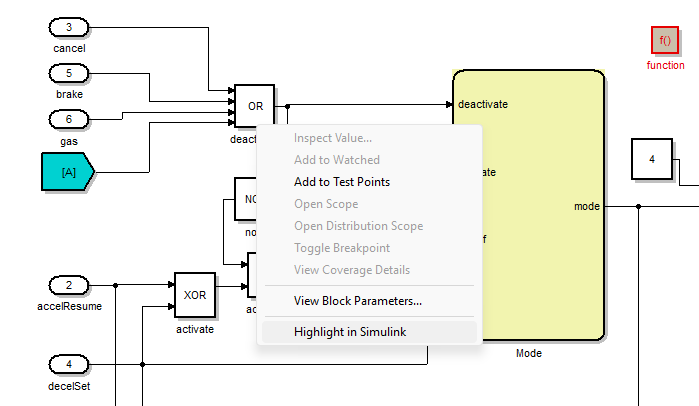
Fig. 4.14 Right-clicking on a block gives the menu option Highlight in Simulink. In addition to blocks, this option is also available when right-clicking on states and transitions.#
4.14.3. MATLAB Version to Open Current Model in Simulink#
You may have multiple versions of MATLAB/Simulink installed on your computer. When Reactis opens the current model in Simulink, it determines the version of MATLAB to use as follows.
No MATLAB windows are currently open. If the version of Simulink used to create the model is installed, it will be used. If that version of Simulink is not installed, Reactis searches for the oldest Simulink version that supports the model format. For example, if a model is created using R2020b, but R2020b is not installed, then Reactis checks for R2021a, then R2021b until it finds a version suitable for the model.
A MATLAB window (previously opened by Reactis) in which the current model CAN be loaded is open. In this case, Reactis will do the highlighting using the existing window.
A MATLAB window (previously opened by Reactis) in which the current model CAN NOT be loaded is open. In this case, a new MATLAB window will open that supports the model. The MATLAB version will be selected as described in item 1 above.
A MATLAB window is open, but it was not started by Reactis. In this case, Reactis shows a message and the user can choose to either have Reactis use this MATLAB window or start a new one.
4.15. Project Viewer Window#
The project viewer window displays information about individial projects and the search path derived from the projects in the reference hierarchy.
4.15.1. Project Properties#
Under the Projects tab, the project viewer window displays the project hierarchy tree and information about the project selected in the tree, as shown in Figure 4.15 (for the root project) and Figure 4.16 (for a referenced project).

Fig. 4.15 The Project Viewer Window displaying information about the root project#

Fig. 4.16 The Project Viewer Window displaying information about a referenced project#
4.15.2. Project Search Path#
Under the Search Path tab, the project viewer window displays the project search path,
as shown in Figure 4.17.
This path contains a list of folders in which
Reactis will search for files such as Simulink model libraries (.slx),
MATLAB scripts (.m), and S-Functions (.dll, .mexw32, .m)
when the current project is loaded. The order in
which folders are listed in the dialog indicates the search order (from top
to bottom).
The path is constructed automatically by adding the path of each project
in the project hierarchy tree.
The path of a project is prepended after the paths of its references,
so occurs above the paths of its references.
The order of the folders cannot be adjusted.
Note
Reactis uses other paths when searching for files. The complete search path is constructed by concatenating:
the model-specific search path, which is specific to the loaded model,
the project search path, described here, if a project is loaded, and
the global search path,
in the order specified above. The model-specific path is set using the Reactis Info File Editor. The global search path is set in the Global Settings.

Fig. 4.17 The Project Viewer Window displaying the overall search path#
4.16. Model Comments#
Model Comments gives you a mechanism for annotating a model under test without making any changes to the model itself. To insert a comment:
Select a subsystem in the Reactis hierarchy panel where the comment should reside
In the Reactis main panel, right-click at the location you prefer to place the comment and select Add Comment…
In the resulting dialog enter the desired comment text (and perhaps an optional comment name)
After a comment is inserted in a model, it appears as a yellow rectangle with the upper right corner folded (somewhat like a sticky note). You can do the following with model comments:
Create a new comment in any subsystem of a model.
View a comment which was previously added.
Edit and make revisions to a comment.
Move or resize a comment.
Cut, or Copy a comment to the clipboard.
Paste a comment from the clipboard.
Remove a comment.
4.16.1. Adding a Comment#
To add a comment, right click in empty space in the main panel, then select Add Comment…. This will open an instance of the Comment Editor, which will be similar in appearance to Figure Figure 4.18.
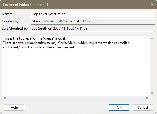
Fig. 4.18 The Comment Editor.#
There are four values displayed in the main panel of the Comment Editor:
Name. The name of the comment. This is optional and can be left empty. Comment names are not required to be unique.
Created by. The user who created the comment and the time when it was created. This is automatically filled in by Reactis and cannot be changed. The user name is taken from Reactis’ global settings.
Last Modified by.The user who last modified the comment and the time when it was modified. This is automatically filled in by Reactis and cannot be changed. The user name is taken from Reactis’ global settings.
The comment text. The large area where you enter the comment text.
There are two ways to close the Comment Editor. Click on OK if you are satisfied with the comment and want to save it. Click on Cancel to close the editor without saving.
4.16.2. Viewing Comments#
Once a comment has been created, it will appear as a sticky note at the point where you right clicked. To quickly view the comment, hover over it with the mouse and a tooltip will appear with comment text, as shown in Figure Figure 4.19. Note that when the comment is viewed this way, it will be clipped if it is large.
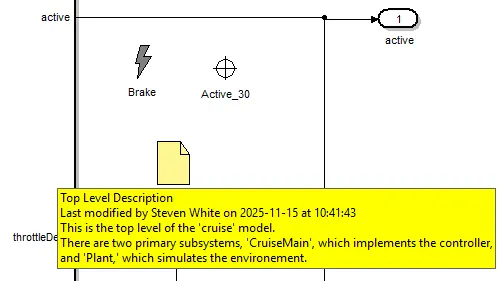
Fig. 4.19 Viewing a comment by hovering over it.#
You can also view the comment by double-clicking on it or right-clicking on it and selecting Edit Comment…. This will open the Comment Editor. You can then see the entire comment in the editor, and close the editor when you are finished reading the comment.
4.16.3. Editing Comments#
To edit a comment, right click on it and select Edit Comment… from the pop up menu. This will open the Comment Editor. In the editor, can change the name and text of the comment as desired, then click on OK to save the changes, or Cancel to close the editor without saving.
4.16.4. Moving and Resizing Comments#
To move a comment within the current displayed subsystem, left-click on it and drag it.
To resize a comment, first left-click on it to cause a blue border to appear around the edges of the comment. This border includes eight blue squares, one on each corner and one in the middle of each border. Left-click on a blue square and drag to resize the comment.
4.16.5. Copying, Cutting, and Pasting Comments#
If you want to move a comment to a different subsystem, you will need to cut the comment from its current subsystem, then navigate to the subsystem where you want to place the comment and paste it there.
To copy a comment to the clipboard, right click on and select Copy from the pop up menu that appears. This will copy the comment to the clipboard.
To cut a comment from the model, right click on it and select Cut from the pop up menu. This will copy the comment to the clipboard and remove it from the model.
To paste a comment from the clipboard, right click on the location where you want the comment to appear and select Paste from the pop up menu. This will create a comment identical to the comment stored in the clipboard, with the exception that the time of last modification and the user name who performed the last modification will be updated.
Note that you can paste as many copies of a comment as you wish.
4.16.6. Removing Comments#
To remove a comment, right click on it and select Remove from the pop up menu.
The comment will disappear from the main panel and removed from the .rsi file.
4.16.7. Undoing Changes to a Comment#
All comment changes can be undone by clicking on the Undo icon in the toolbar.
Comment changes which were previously undone can be restored by clicking on the
Redo icon. When the .rsi file is saved, all changes become permanent and cannot
be undone, so be careful when saving the .rsi file.
4.16.8. Comment ID Numbers#
Reactis automatically assigns a unique ID number to each comment. These are used to identify comments which would otherwise be identical. When a comment is edited, the ID number is displayed in the title bar of the Comment Editor.