3. Advanced Model Validation#
The model-validation capabilities of Reactis help engineers detect bugs earlier, when they are less costly to fix.
A primary benefit of model-based design is that it allows the detection and correction of system-design defects at design (i.e. modeling) time, when they are much less expensive and time consuming to correct, rather than at system-implementation and testing time. Moreover, with proper tool support, the probability of detecting defects at the model level can be significantly increased. In this section, we elaborate on the advanced model-validation capabilities of Reactis that help engineers build better models.
3.1. Debugging with Tester and Simulator#
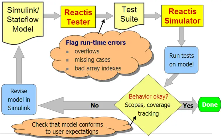
Reactis Tester and Simulator support model debugging through the automatic generation of test suites that thoroughly exercise the model under investigation (Reactis Tester), and through the visualization of tests as they are executed on the model (Reactis Simulator). One such usage scenario of Tester and Simulator is shown in Figure 3.1. Since Tester’s guided-simulation test-generation algorithm thoroughly simulates a model during test generation, it often uncovers runtime errors. For example, overflows, missing cases, and bad array indexes can be discovered. Note that this type of error is also detected when running simulations in Simulink; however, since Tester’s guided-simulation engine systematically exercises the model much more thoroughly than random simulation can, the probability of finding such modeling problems is much higher using Reactis.

Fig. 3.1 Debugging Simulink models with Reactis Tester and Reactis Simulator#
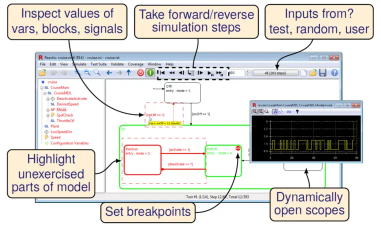
Tester-generated tests may be executed in Simulator, which offers a number of useful model debugging features; some of these are illustrated in Figure 3.2. The figure includes a screenshot of Reactis invoked on a Simulink/Stateflow model of an automotive cruise control system. This example is one of several example applications included with the Reactis distribution. The main window in the figure depicts the model hierarchy on the left and an execution snapshot of a Stateflow diagram from the model on the right. Reactis allows you to choose between three distinct sources of input values when visualizing model execution. Input values may be:
read from a Tester-generated test,
generated randomly,
supplied interactively by the user.
Model-debugging facilities illustrated in the figure are as follows.
You may take forward or reverse execution steps when simulating model behavior.
You may dynamically open scopes to view the values of Stateflow variables or Simulink blocks and signals. An example scope, depicting how the value of Stateflow variable mode varies over time, is shown. This scope was opened by right-clicking on the mode variable in the diagram panel and selecting Open Scope.
You may query the current value of any Simulink block or signal, Stateflow variable, or C variable by hovering over it with the mouse.
You may set execution breakpoints. In the example, a breakpoint has been set in state Active. Therefore, model execution will be suspended when control reaches this state during simulation, allowing the user to carefully examine the model before continuing simulation. Simulation may be resumed in any input mode, i.e. reading inputs from the test, generating them randomly, or querying the user for them.
As shown in the execution snapshot, the current simulation state of the model is highlighted in green and portions of the model that have not yet been exercised during simulation are highlighted in red for easy recognition.

Fig. 3.2 Reactis Simulator offers an advanced debug environment for Simulink models.#
3.2. Validating Models with Validator#
The advanced model-validation capabilities of Reactis are implemented in Reactis Validator. Validator searches for defects and inconsistencies in models. The tool lets you formulate a requirement as an assertion, attach the assertion to a model, and perform an automated search for a simulation of the model that leads to a violation of the assertion. If Validator finds an assertion violation, it returns a test that leads to the problem. This test may then be executed in Reactis Simulator to gain an understanding of the sequence of events that leads to the problem. Validator also offers an alternative usage under which the tool searches for tests that exercise user-defined coverage targets. The tool enables the early detection of design errors and inconsistencies and reduces the effort required for design reviews.

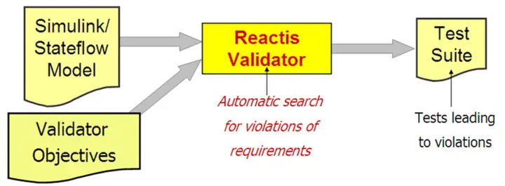
Fig. 3.3 Reactis Validator automates functional testing.#
Figure 3.3 shows how engineers use Validator. First, a model is instrumented with assertions to be checked and user-defined coverage targets. In the following discussion, we will refer to such assertions and coverage targets as Validator objectives. The tool is then invoked on the instrumented model to search for assertion violations and paths leading to the specified coverage targets. The output of a Validator run is a test suite that includes tests leading to objectives found during the analysis. Validator objectives may be added to any Simulink system or Stateflow diagram in a model.
Two mechanisms for formulating objectives in Simulink models are supported: Expression objectives are C-like boolean expressions. Diagram objectives are Simulink / Stateflow observer diagrams.
Diagram objectives are attached to a model using the Reactis GUI to specify a Simulink system from a library and “wire” it into the model. The diagrams are created using Simulink and Stateflow in the same way standard models are built. After adding a diagram objective to a model, the diagram will be included in the model’s hierarchy tree, just as library links are in a model. Note that the diagram objectives are stored in a separate library and the .slx file containing the controller model remains unchanged.
Because of its sophisticated model-debugging capabilities, the Reactis tool suite provides significant added value to the MathWorks Simulink/Stateflow modeling environment. The great virtue of model-level debugging is that it enables engineers to debug a software design before any source code is generated. The earlier logic errors are detected, the less costly they are to fix.