6. The Reactis Harness Editor#
Reactis does not modify your C source files. Instead the tool stores
project-specific information that it requires in a Reactis Harness
Library (.rsh file). The primary way for users to view and edit the
data in these files is via the Reactis Harness Editor, as described in
this chapter. The key components of a harness are inputs, outputs, an
initialization function, and an entry function. To construct a test
for a harness, Reactis for C first calls the initialization
function. It then repeatedly performs the following steps:
Selects values for each harness input.
Calls the entry function with the selected inputs.
Records the generated outputs.
Each harness library contains one or more harnesses. As shown in
Figure 6.1, the harness selector in the
toolbar of the Reactis Harness Editor enables the user to select a
harness from those defined in the currently loaded .rsh file, to
create a new harness, or to delete a harness. The currently selected
harness is displayed in parentheses beside the .rsh file name in the
title bars of the main window and harness editor.
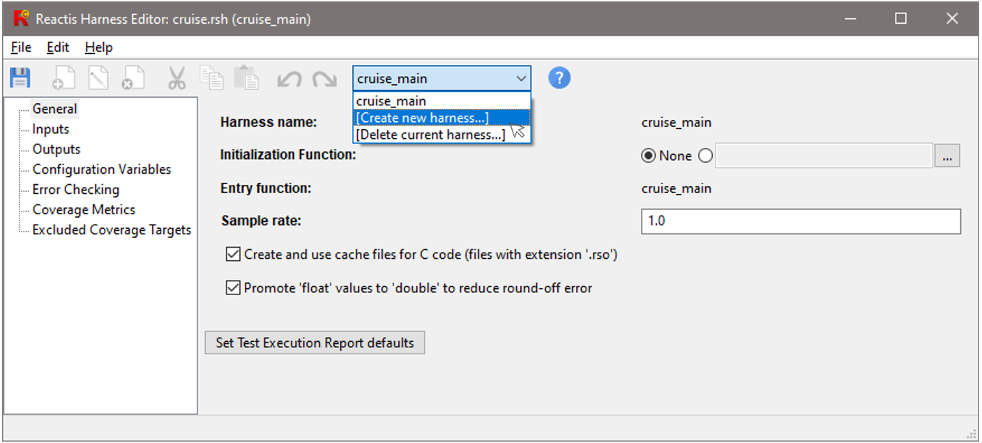
Fig. 6.1 The Reactis Harness Editor.#
The Reactis Harness Editor contains seven panes used to control different aspects of testing:
- General
Displays the initialization function, entry function, harness name, sample rate, and some additional settings which control simulation. The initialization function is called once per test, and the entry function is called once per step during simulation and testing.
- Inputs
A set of variables used as inputs. A new value is generated for each input prior to taking a step during simulation or test-generation. The user may constrain the set of allowed values for each input.
- Outputs
A set of variables used as outputs. After each step the values of the outputs are recorded.
- Configuration Variables
A set of variables which may change prior to the start of a test, but not during a test.
- Error Checking
Settings which specify the action to take when an anomalous condition, such as a numeric overflow, occurs.
- Coverage Metrics
Settings that specify which coverage metrics will be tracked during simulation and the details of each metric.
- Excluded Coverage Targets
A set of coverage targets which are excluded from coverage tracking.
Note that the contents of an .rsh file may only be modified when
Simulator is disabled. When Simulator is running, the Reactis Harness
Editor operates in read-only mode as indicated by the appearance of
[read only] in the editor window’s title bar.
Although not necessary, the default naming convention assumes that the
.rsm file and .rsh file of a project share the same base name; for
example, if the .rsm file is named cruise.rsm, then the name of
the associated .rsh file is assumed to be cruise.rsh. A .rsh file
named differently may be associated with a program by loading the
build file in Reactis and selecting File > Select Harness Library….
6.1. Creating a new harness#
To create a new harness, either select Edit > New Harness… within the main Reactis for C window or select the Create new harness… option in the harness selector drop-down box. This will bring up the dialog shown in Figure 6.2.
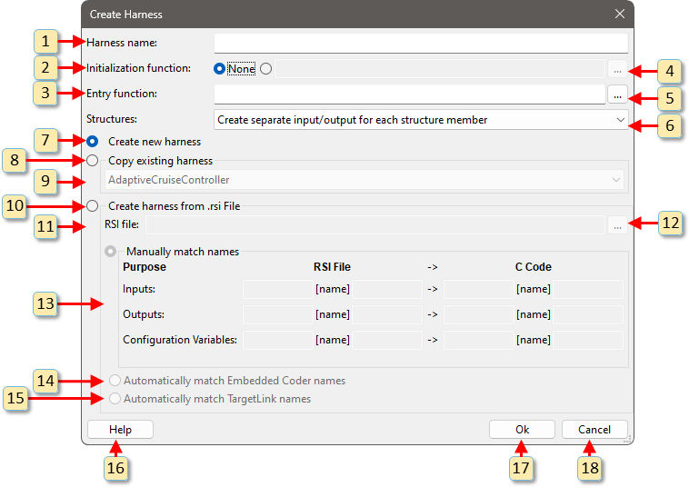
Fig. 6.2 The Create Harness dialog.#
The numbered items in Figure 6.2 let you specify a harness as follows:
Harness name Specify a name for the harness being created in this entry box.
Initialization function Each harness has an initialization function – a function that Reactis for C will call once per test, before the first step of the test is taken. The initialization function can either be set to None, or the name of a function can be entered into the text entry box.
Entry function This text entry box lets you specify an entry function, which Reactis for C will call for every step in a test. To construct a test for a harness, Reactis for C repeatedly:
a. Selects values for each harness input.
b. Calls the entry function with the selected inputs.
c. Records the generated outputs.
… Clicking this button opens a dialog that lets you select an entry function from a list of candidate functions.
… Clicking this button opens a dialog that lets you select an initialization function from a list of candidate functions. Only functions which have no arguments and do not return a value can to be used as initialization functions.
Create separate input/output for each structure member This menu determines how structures in the test harness are handled and has two choices: (1) split the structure into a separate input or output for each member of the structure, or (2) create a single input or output for the entire structure.
Create new harness Creates a new harness with the minimum set of inputs and outputs, as inferred from the entry function’s parameters and return value type:
Each pass-by-value argument to the entry function is added as an input.
Each pass-by-reference argument to the entry function is added as an output
If the entry function’s return value type is non-void then an output is added for the return value.
Copy existing harness Copies inputs, outputs and configuration variables from an existing harness in the current harness library. This can be useful when defining harnesses for different entry functions that share some of the inputs, outputs and configuration variables.
When Copy existing harness is selected, this menu lets you specify the harness to copy.
Create harness from .rsi file Copy inputs, outputs, and configuration variables from an .rsi file created with Reactis for Simulink for a Simulink model. This option is useful if test cases for the model have been created with Reactis for Simulink and C code was automatically generated from the model. When a harness is constructed with this option, tests generated from the model can be directly run on the C code with Reactis for C.
RSI file If copying harness info from an .rsi file, enter the .rsi file name in this text box.
… Open a file selection dialog to specify an .rsi file from which to copy harness info.
Variable Renaming The names of Simulink inports and outports might not match exactly with the names of corresponding variables in the C code. The Variable Renaming section of the dialog provides a way to map the names to resolve any differences. Using the text boxes in this section, you can specify common prefixes or suffixes for the items in the .rsi file and/or the C code. For each inport/outport/configuration variable in an .rsi file, the following process is used to try to map it to an item in the C code:
a. \(itemname_{1}\) = the name of the inport/outport/configuration variable as found in the .rsi file.
b. \(itemname_{2}\) = the result of removing the prefix specified in the RSI File prefix column from the beginning of \(itemname_{1}\).
c. \(itemname_{3}\) = the result of removing the suffix specified in the RSI File suffix column from the end of \(itemname_{2}\).
d. \(itemname_{4}\) = the result of adding the prefix specified in the C Code prefix column to the beginning of \(itemname_{3}\).
e. \(itemname_{5}\) = the result of adding the suffix specified in the C Code suffix column to the end of \(itemname_{4}\).
f. In the C code, if a global variable or parameter of the entry function is named \(itemname_{5}\) then it will be added as an input/output/configuration to the harness. Its harness name will be \(itemname_{1}\) and it will map to C code item \(itemname_{5}\). If \(itemname_{5}\) does not match any global variable or entry function parameter, then Reactis will produce a warning that a match could not be found.
Figure 6.3 shows some mapping examples:
- Example A
Mapping inport/outport names with prefixes or suffixes to C variables: Simulink inports named “SLin_name” will map to “name” in the C code. Simulink outports named “name_SLout” will map to “name” in the C code.
- Example B
Mapping inport/outport names to C variables with prefixes or suffixes: Simulink inports named “name” will map to “Cin_name” in the C code. Simulink outports named “name” will map to “name_Cout” in the C code.
- Example C
Mapping with prefixes or suffixes in both inport names and C variables: Simulink inports named “SLPrefix_name_SLSuffix” will map to “CPrefix_name_CSuffix” in the C code.
Automatically match embedded coder functions/variables. If the C code was produced using MATLAB Embedded Coder, checking this box will automatically apply renaming rules which match model names to code names.
Automatically match TargetLink functions/variables. If the C code was produced using dSPACE TargetLink, checking this box will automatically apply renaming rules which match model names to code names.
Help Clicking this button opens the help dialog.
Ok Clicking this button causes the harness creation to proceed.
Cancel Clicking this button closes the dialog without creating a harness.
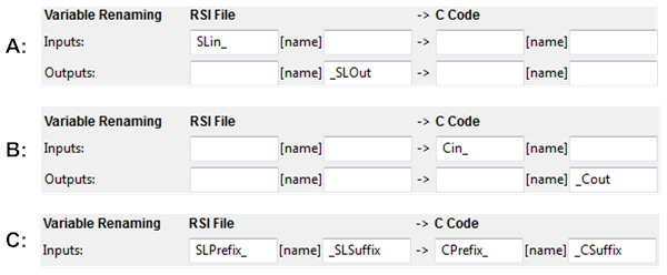
Fig. 6.3 Examples for different mapping configurations#
6.2. General Pane#
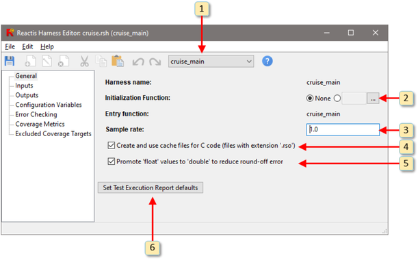
Fig. 6.4 The General pane of the Reactis Harness Editor#
The General tab of the harness editor is shown in Figure 6.4. The settings controlled by this tab are labeled 1 through 6 in Figure 6.4.
cruise_mainThis pull-down menu is used to select the current harness, create a new harness, or delete the current harness. The displayed value is the name of the current harness.Initialization Function The initialization function is called at the start of each test.
Sample rate The sample rate is the number of seconds to add to the time (t) at the end of each step. When performing back-to-back testing, the test harness sample rate will typically match the sample rate of the model.
Create and use cache files for C code When checked, Reactis will generate a Reactis object file for each C source file. These files have extension
.rsoand are stored in the directory containing the C source file from which they were compiled. Subsequently, the C source file will only be recompiled if it is modified or if a new version of Reactis is installed.Promote ’float’ values to ’double’ to reduce round-off error. When checked, single-precision floating-point values will always be converted to double-precision prior to any calculation, which reduces round-off error in some cases. For strict C99 compliance, this should be disabled (not checked).
Set Test Execution Report defaults This button opens a dialog which controls the default settings for test execution reports.
6.3. Inputs Pane#
The Inputs tab (see Figure 6.5) of the harness editor enables you to define a set of inputs. Inputs are either parameters to the entry function or global variables which are designated as inputs by selecting Edit > Add… and then choosing from the candidate list. Parameters which are passed by reference can also be designed as inputs via the the same mechanism.
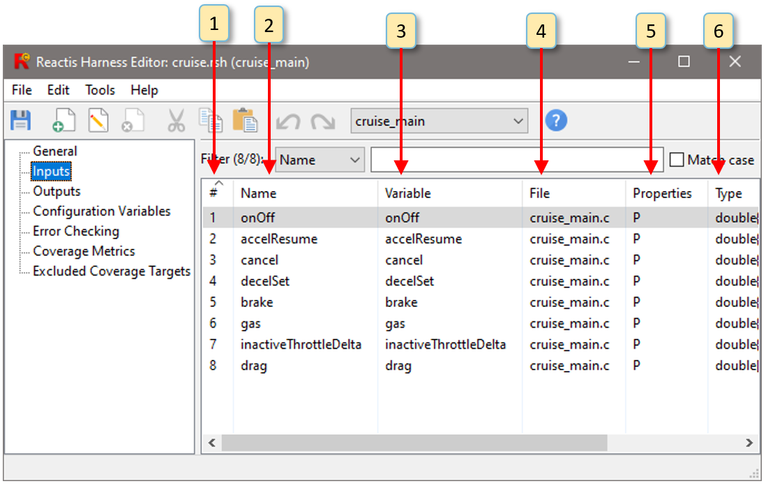
Fig. 6.5 The Inputs tab of the harness editor defines the set of inputs and limits on the values that the inputs can assume during simulation and test generation.#
The Inputs tab contains six columns for each input value. These are numbered 1 through 6 in Figure 6.5. The purpose of each column is as follows:
# The number of the input (1 … N).
Name The name of an input is usually, but not always, the same as the name of the variable which holds the input value. See the Names section for details.
Variable The name of the variable which holds the input value.
File The name of source file in which the variable which holds the input value is defined.
Properties A code which describes how the input is passed through the harness and stored in the program under test. See the Properties section for details.
Type This field specifies the set of values that can be assigned to the input. See the Types section for details.
6.4. Outputs Pane#
The Outputs tab of the harness editor enables the user to add and remove items to the set of outputs. A value is recorded for each output at the end of each simulation step as tests are constructed. By default all pass-by-reference parameters of the entry function are considered outputs, but they may be removed from the list and global variables may be added. When the Outputs tab is displayed, entries from the Edit menu may be used to add or remove items to/from the list.
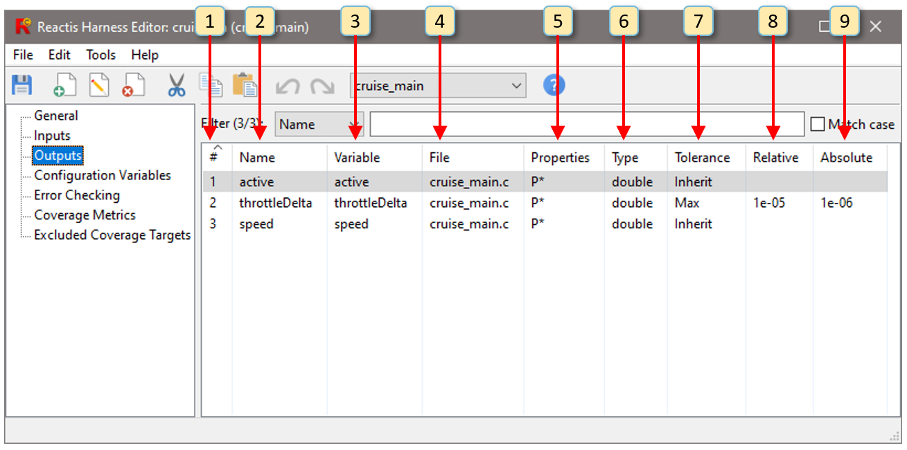
Fig. 6.6 The Outputs pane of the harness editor.#
The Outputs tab contains six columns for each input value. These are numbered 1 through 9 in Figure 6.6. The purpose of each column is as follows:
# The number of the output (1 … N).
Name The name of an output is usually, but not always, the same as the name of the variable which holds the output value. See the Names section for details.
Variable The name of the variable which holds the output value.
File The name of source file in which the variable which holds the output value is defined.
Properties A code which describes how the output is stored in the program under test and passed through the harness. See the Properties section for details.
Type The type of the output. Double clicking opens a type editor dialog from which the type can be changed.
Tolerance The tolerance method to use when comparing an actual output value with the value in a test suite (see the Tolerance Methods section).
Relative The relative tolerance value. If the method does not use relative tolerance, this will be blank.
Absolute The absolute tolerance value. If the method does not use absolute tolerance, this will be blank.
6.4.1. Tolerance Methods#
There are five methods for computing the tolerance: Absolute, Relative, Max, Min, and Inherit.
The absolute tolerance method flags a difference between a computed value and a test value if the absolute value of the difference exceeds a given amount. More precisely, given two values x and y and an absolute tolerance є, the difference between x and y is flagged if and only if |x−y| > є.
The relative tolerance method flags a difference between a computed value and a test value if it exceeds an amount determined by multiplying the tolerance by either the computed or test value. More precisely, given two values x and y and a relative tolerance є, the difference between x and y is flagged if and only if any of the following conditions are true:
|x−y| > є × | x | when x ≠ 0
|x−y| > є × | y | when y ≠ 0
|x−y| > \(є^2\) when x = 0 or y = 0
A relative or absolute tolerance of zero will require that the model and test values always be the same, a relative tolerance of 0.1 will allow a difference of 10%, and a relative tolerance of 1 will allow the model value to be at most twice the test value.
The max tolerance method uses both a relative and absolute tolerance. A difference is flagged only if it is flagged by both the absolute and relative tolerance methods.
The min tolerance method uses both a relative and absolute tolerance. A difference is flagged if it is flagged by either the absolute or relative tolerance method.
If the tolerance method is set to Inherit, then the tolerance method is inherited from the model’s global tolerance setting (set in the Error Checking pane of the Reactis Harness Editor).
6.5. The Tolerance Editor Dialog#
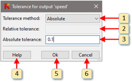
Fig. 6.7 The dialog for specifying the tolerance to use when comparing computed
and test suite values. As shown, an absolute tolerance of 0.1 is
specified for port speed, which means that differences which are less
than or equal to 0.1 will be ignored.#
Tolerances are specified via the tolerance editor dialog, which is shown in Figure 6.7. The labeled items in Figure 6.7 are explained as follows:
This pull-down menu lets you choose the tolerance method. The possible choices are Inherit, Relative, Absolute, Min, or Max. These are explained in the Tolerance Methods section.
This data entry box contains the relative tolerance value used by the selected method, which must be non-negative. If the method does not use relative tolerance, it will be disabled.
This data entry box contains the absolute tolerance value used by the selected method, which must be non-negative. If the method does not use absolute tolerance, it will be disabled.
This button opens the help dialog for the tolerance editor dialog.
This button accepts the displayed tolerance value and closes the tolerance editor dialog.
This button ignores any changes made to the tolerance and closes the tolerance editor dialog.
6.6. Configuration Variables Pane#
Configuration variable directives allow certain scalar global variables to be treated as “configuration variables” whose values can only change between tests (but not during a test).
A configuration variable is created by clicking on Edit >
Configuration Variables… in the main Reactis window, then selecting
Edit > Add… in the menu bar of the Reactis Harness Editor window
that comes up. Reactis will display a list of all candidate
configuration variables which users may select from. The types
associated with these configuration variables in .rsh files are the
same as those that may be assigned to inputs. Note, however, that
configuration variables may not be given delta types, since the
variables are not allowed to change during a test or simulation run.
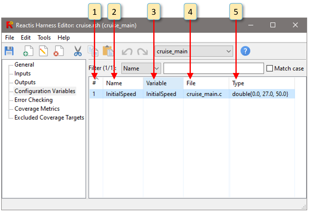
Fig. 6.8 The Configuration Variables tab of the harness editor.#
As shown in Figure 6.8, the Configuration Variables tab has five columns, whose meaning is as follows:
# The number of the configuration variables (1 … N).
Name A user-defined name which is usually, but not necessarily then as the name of variable. See the Names section for details.
Variable The name of the configuration variable in the source code.
File The name of source file in which the configuration variable is defined.
Type This field specifies the set of values that can be assigned to the configuration variable. See the Types section for details.
6.7. Names#
The Inputs, Outputs and Configuration Variables tabs of the Reactis Harness Editor have columns titled Name and Variable. Both of these columns contain names. The name displayed in the Variable field is the actual name of the variable in the source code. This name cannot be changed and does not have to be unique. The name displayed in the Name field, on the other hand, can be changed and must be unique.
6.8. Properties#
The Inputs and Outputs tabs of the Reactis Harness Editor have a
column labeled Properties, which contains a code describing how each
input and output is passed through the harness and stored in the
program under test. There are four property codes, P, P*, R and G,
whose meaning is given by the following table:
Code |
Meaning |
|---|---|
P |
Pass-by-value parameter to entry function. |
P* |
Pass-by-reference parameter to entry function. |
R |
Return value of entry function. |
G |
Global variable. |
6.9. Types#
The Inputs, Outputs and Configuration Variables tabs of the Reactis Harness Editor have a column labeled Types. The Types column contains type specifications. For inputs and configuration variables, the type specification determines what values may be assigned to the variable during simulation, test generation and validation. The initial type specification for each variable is the equivalent of its C type. This indicates that the full range of values which the variable can hold should be generated during testing. In many cases, the set of desired input values is actually smaller than the full range of the C type. For example, an input may have a type of char, but may actually be used as a Boolean value whose allowed values are 0 or 1. If this is the case, then editing the type specification will significantly improve coverage results during testing.
Note that for outputs, the type specification for an input is permanently fixed to the equivalent to its C type.
Type specifications can be changed from the Inputs and Configuration
Variables tabs of the harness editor. A type specification starts with
a base type, which is selected from the list: int8, int16, int32,
uint8, uint16, uint32, double, single.
A base type can then be extended by notation to specify (1) ranges and subsets within a base type, (2) rate-of-change (or delta) constraints, (3) resolution constraints and (4) array types. The full set of type specifications is defined by the following grammar (in which rsiType is the starting symbol).
intType |
: |
|
floatType |
: |
|
fixedPointType |
: |
|
| |
|
|
numberType |
: |
intType |
| |
floatType |
|
| |
fixedPointType |
|
baseType |
: |
numberType |
| |
|
|
rsiType |
: |
baseType |
| |
\(baseType \{ val_{1}, val_{2}, ... , val_{n} \}\) |
|
| |
numberType [ min, max ] |
|
| |
numberType |
|
| |
numberType [ min, max ] |
|
| |
floatType [ min : step : max ] |
|
| |
floatType [ min : step : max ] |
|
| |
<| \(rsiType_{1} * rsiType_{2} * ... * rsiType_{n}\) |> |
|
| |
vectorType |
|
| |
structType |
|
vectorType |
: |
<| \(rsiType_{1} * rsiType_{2} * ... * rsiType_{n}\) |> |
structType |
: |
{ \(fieldName_{1} : rsiType_{1} , ... , fieldName_{m} : rsiType_{m}\) } |
| |
structName > { \(fieldName_{1} : rsiType_{1} , ... , fieldName_{m} : rsiType_{m}\) } |
|
val |
: |
value |
| |
value : weight |
The variables in this grammar are defined as follows. min, max, step, and value are elements of the given base type, weight is an integer greater than zero and less than one thousand. For a vector type \( <| rsiType_{1} * rsiType_{2} * ... * rsiType_{n} |>\), the base types of all \(rsiType_{i}\) must be identical. For a structure type, the base types of the different field types \(rsiType_{i}\) may be different.
Fixed point types are strings that specify a set of parameters for the
generalized slope-bias encoding scheme for representing real numbers
using integers. These strings consist of a prefix of either sfix
(signed) or ufix (unsigned) followed by a suffix of the form
bitsSlopeBias. The suffix is further divided into one required
substring bits and two optional substrings slope and bias. These
three substrings are defined as described below. Note that fpDecimal
is a string that encodes a decimal value by replacing a negative sign
“-” with “n” and the decimal point “.” with “p”. For example, “-4.9”
is represented as “n4p9” and “2.3” as “2p3”. Similarly fpInt is a
string that encodes an integer value by replacing a negative sign “-”
with “n”.
- bits
is a positive integer indicating the number of bits to be used to represent values of the type.
- slope
is a decimal specified in one of two ways
as
_SfpDecimal such that \(slope = fpDecimal\)as
_FfpDecimal_EfpInt such that \(slope = fpDecimal×2^{fpInt}\)
- bias
is a decimal specified as
_BfpDecimal.
If the slope substring is omitted a default value of 1 is used. If the bias substring is omitted a default value of 0 is used.
The following examples show some legal types and the sets of values they specify.
RSI Type |
Values in Type |
|---|---|
|
All double-precision floating-point numbers |
|
|
|
|
|
|
|
|
|
|
|
All double-precision floating-point numbers, but input values of this type can increase or decrease by at most 1.0 during successive simulation steps. |
|
|
|
|
In range types (i.e. those of form \(t[l,u]\)) the lower and upper
bounds are inclusive. In enumeration types (i.e. those of form
\(t\{u_{1}, …, u_{n}\}\)) the probability weights in the \(u_{i}\) enable
the user to influence the probabilities of the different values in
the type being selected during simulation, test generation, and C
code validation. For example, an input having type uint8 {0:1, 1:3}
would be assigned the value 0 in 25% of random simulation steps and
the value 1 in 75% of random simulation steps, on average. In
general, if input \(x\) is assigned the type \(t\{ v_{1}:w_{1},
v_{2}:w_{2}, ..., v_{n}:w_{n}\}\), then the probability of each value
in the type being assigned to \(x\) is computed as follows. Let \(W =
w_{1} + w_{2} + ... + w_{n}\), where \(w_{i}\) denotes the probability
weight assigned to \(v_{i}\) (a weight of 1 is assumed if no explicit
weight is given). During “random” simulation or test generation, the
probability of an input \(x\) being assigned the value \(v_{i}\) is
\(w_{i}/W\).
Using delta types (i.e. those of form t delta [l,u]) users may
constrain how the values fed into inputs change from one simulation
step to the next. For example, an input representing a sensor
measuring temperature might have the type double delta [-1.0,1.0] to
specify that temperature can either increase or decrease by at most 1
degree between any consecutive simulation steps. In general, if input
\(x\) has type t delta [l,u] and the current value of \(x\) is \(v_{1}\)
then in the next simulation step the new value, \(v_{2}\), of \(x\) must
satisfy: \(v_{1} + l <= v_{2} <= v_{1} + u\).
Using resolution types (i.e. those of form double [i:j:k] where i is a
lower bound, j is a resolution, and k is an upper bound) users may
specify that each value that a variable of this type may assume will
differ from i by some multiple of j. A delta constraint may also be
added to a resolution type.
6.10. The Type Editor Dialog#
The Type Editor Dialog, shown in Figure 6.9, helps users construct types for inputs and configuration variables. In the following discussion, we use TUC to denote the type under construction, i.e. the type currently being defined with the dialog.
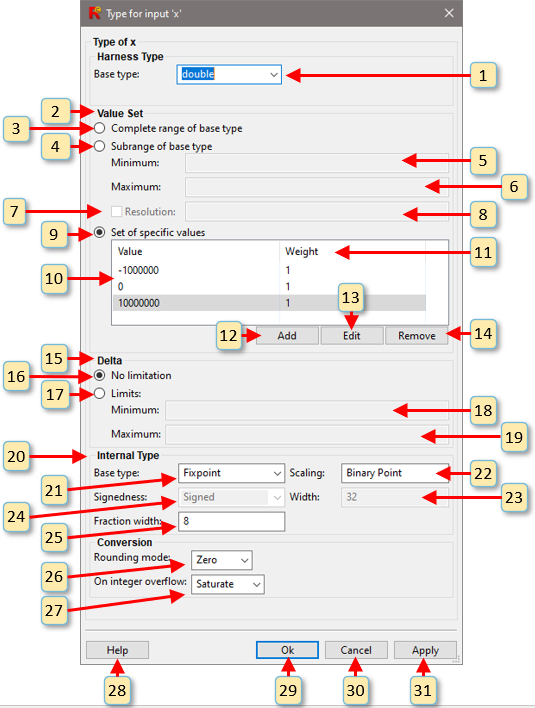
Fig. 6.9 The dialog for specifying type information for inputs or configuration variables. As shown here a type of double is specified for input x which will be converted to fixed-point before being stored in the memory of the program under test. Furthermore, the input values for x have been constrained to the set { −10000000.0, 0.0, 10000000.0 }. During random simulation, x will be assigned one of these three values with equal probability.#
The Type Editor may be invoked from either the Inputs or Configuration Variables tabs and selecting an input or configuration variable row with a single click, and then right-clicking in the body of the Reactis Harness Editor and selecting Edit Type, or selecting menu item Edit > Edit….
6.10.1. Using the Type Editor#
A type may be constructed with the dialog by performing the following steps. Recall that TUC denotes type under construction, i.e. the type currently being defined with the dialog. The process for editing a type works as follows:
Do you wish to use a type in the test harness which is different from the type in the C source code?
- No.
Leave the harness base type unchanged (it will initially match the internal base type) and proceed to step 2.
- Yes.
Use the pull-down menu (item 1 in Figure 6.9) to select the desired type and proceed to step 2.
Should the values chosen during simulation include all values in the base type, only a subrange of the base type, or only a set of specific values in the base type?
- All values in base type.
Select the Complete range of base type radio button (item 3 in Figure 6.9) and proceed to step 3.
- Only a subrange of the base type.
Select the Subrange of base type radio button (item 4 in Figure 6.9) and specify a lower and upper bound for the range using window items 5 and 6 respectively. If the input has a base type of
doubleorsingle, then you may specify a resolution for the values in the TUC. To do so click the Resolution check box (item 7 in Figure 6.9) and enter a resolution value in the text box to the right (item 8 in Figure 6.9). When a resolution is specified, a variable of the TUC will only assume values that differ from the lower bound (item 5 in Figure 6.9) by some multiple of the resolution value (item 8 in Figure 6.9). Proceed to step 3.- A specific set of values in the base type.
Select the Set of specific values radio button (item 9 in Figure 6.9) and use the Add, Edit, and Remove buttons (items 12, 13, and 14 in Figure 6.9) to create a list of values. Each value must be an element of the base type of the TUC and may be assigned a probability weight. See the Inputs section for a description of probability weights. Proceed to step 3.
Do you wish to constrain how the values fed into the input parameter may change from one step to the next during simulation?
- No.
Select the Complete radio button (item 16 in Figure 6.9) and proceed to step 4.
- Yes.
Select the Limits radio button (item 17 in Figure 6.9) and enter values in the Minimum and Maximum text entry boxes (items 18 and 19 in Figure 6.9). If \(min\) and \(max\) are the values specified here, then values fed into the entry function parameter with the TUC will be constrained as follows. If \(v_{1}\) and \(v_{2}\) are values for such a port in consecutive simulation steps, then \(v_{1} + min <= v_{2} <= v_{1} + max\) . Proceed to step 4.
Does the C code expect a fixed-point value as input?
- No.
Leave the internal type unchanged and proceed to step 5.
- Yes.
Select Fixpoint from the internal base type pull-down menu (item 21 in Figure 6.9), then select a scaling mode (item 22 in Figure 6.9)), and finally the scaling parameters (item 25 in Figure 6.9) Proceed to step 5.
Does the conversion from the harness type to the internal type require rounding or can it overflow?
- No.
Proceed to step 6.
- Yes.
Select a rounding mode (item 26 in Figure 6.9) and/or overflow behavior (item 27 in Figure 6.9)). Proceed to step 6.
When you are satisfied with the type you have constructed click the Ok button to update type and dismiss the Type Editor dialog.
Select File > Save to save your changes to the
.rshfile.
6.10.2. Labeled Window Items#
This section describes the labeled items in Figure 6.9. Recall that TUC denotes type under construction, i.e. the type currently being defined with the dialog.
This pull-down menu changes the base type of the harness variable.
The radio buttons in this group (window items 3, 4, and 9) enable the user to specify the values from the base type to be include in the TUC.
Selecting this radio button indicates that all values from the base type should be included in the TUC.
Selecting this radio button indicates that only a subrange of values from the base type should be included in the TUC.
When the Subrange of base type radio button is selected, this entry box enables the user to specify a lower bound for the subrange.
When the Subrange of base type radio button is selected, this entry box enables the user to specify an upper bound for the subrange.
If the Subrange of base type radio button is selected for a base type of double or single, then this check box may be checked in order to specify a resolution for the TUC.
When the Resolution check box (window item 7) is checked, a resolution value must be entered in this text box. When a resolution is specified, a variable of the TUC will only assume values that differ from the lower bound specified in window item 5 by some multiple of the resolution value here.
Selecting this radio button indicates that only a specified set of values from the base type should be included in the TUC. Window items 10-14 are used to specify the set of values.
The entries in this column enumerate the values in the TUC.
The entries in this column associate a probability weight with each value in the TUC. See the Inputs section for a description of probability weights.
Edit the probability weight for the currently selected value.
Remove the currently selected value.
The radio buttons in this group (window items 16 and 17 enable the user to specify whether or not the type has a delta constraint. For a parameter with the TUC, such a constraint limits the allowable changes in value from one simulation step to the next.
The TUC has no delta constraint.
The value for a parameter with the TUC may change by no less than the value specified here. If \(v_{1}\) and \(v_{2}\) are the values of the parameter in consecutive simulation steps then \(v_{2} − v_{1} >= min\).
The value for a parameter with the TUC may change by no more than the value specified here. \(v_{2} − v_{1} <= max\).
The items in this panel (labeled 21-27 in Figure 6.9)
This pull-down menu changes the internal type from a fixed-point type. It can only be used when the type in the source code is an integer type.
This pull-down menu determines the scaling used when the internal base type is a fixed-point type. Available choices are Binary Point or Slope and Bias.
The signedness of the fixed-point type is displayed here. It matches the signedness of the underlying integer type and cannot be changed.
The width (in bits) of the fixed-point type is displayed here. It matches the width of the underlying integer type and cannot be changed.
When binary point scaling is selected, the fraction width (in bits) of the fixed-point type is entered here. If slope and bias scaling is chosen, the fraction width will be replaced with entries for the slope and bias.
This pull-down menu determines the rounding mode to use when converting values from the harness type to the internal type. Possible choices are Zero, Ceiling, Floor, or Nearest.
This pull-down menu determines the overflow mode to use when converting values from the harness type to the internal type. Possible choices are Saturate or Wrap over.
View help on the type editor dialog.
Update the TUC and dismiss the dialog. The revised TUC will appear in the appropriate row of the Reactis Harness Editor and “[modified]” will appear in the title bar. Selecting File > Save will write the
.rshfile to disk and cause the “[modified]” tag in the title bar to disappear.
Discard any changes to the TUC and dismiss the dialog.
Update the TUC without dismissing the dialog.
6.11. Error Checking Pane#
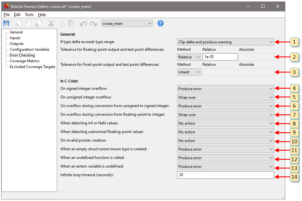
Fig. 6.10 The Error Checking pane of the Reactis Harness Editor.#
The Error Checking pane of the Reactis Harness Editor, shown in Figure 6.10, lets you specify what action to take when anomalous conditions occur during program execution. The settings controlled via this pane are numbered 1-14 in Figure 6.10:
The action to take when a type delta exceeds the range of the type. Possible actions are Clip Delta, Clip delta and Produce warning, or Produce error.
The default tolerance to use when comparing floating-point test suite outputs to program outputs.
The default tolerance to use when comparing fixed-point test suite outputs to program outputs.
The action to take when a signed integer overflow occurs. Possible values are Wrap over, Produce warning, or Produce error.
The action to take when an unsigned integer overflow occurs. Possible values are Wrap over, Produce warning, or Produce error.
The action to take when an overflow occurs while converting an unsigned integer value to signed integer. Possible values are Wrap over, Produce warning, Produce error, or Inherit from “On signed integer overflow”.
The action to take when an overflow occurs while converting an floating point value to (signed or unsigned) integer. Possible values are Wrap over, Produce warning, Produce error, or Inherit from “On signed integer overflow”.
The action to take when a NaN (not-a-number) or infinite value is detected. Possible values are No action, Produce warning, Produce error.
The action to take when a subnormal floating-point value is detected. Possible values are No action, Produce warning, or Produce error.
The action to take when an invalid pointer is detected. Possible values are No action, Produce warning, or Produce error.
The action to take when an empty structure or union type is defined. Possible values are No action, Produce warning, or Produce error.
The action to take when an undefined is called. Possible values are Return zero, or Produce error.
The action to take when an extern variable is never defined. Possible values are Initialize to zero, Produce warning and initialize to zero, or Produce error.
The simulation time limit (in seconds) for a simulation step to finish. A value of 0 makes the step time unlimited.
6.12. Coverage Metrics Pane#
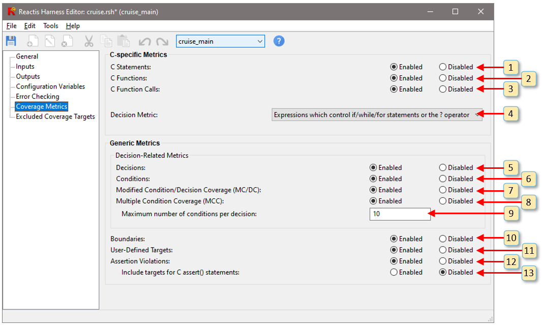
Fig. 6.11 The Coverage Metrics pane of the Reactis Harness Editor.#
The Coverage Metrics pane of the Reactis Harness Editor is used to specify which metrics should be tracked and how they should be tracked. An annotated screenshot of the Coverage Metrics pane appears in Figure 6.11. The following items are labeled Figure 6.11:
This setting enables or disables the C Statement metric. See the Statement Coverage section for details.
This setting enabled or disabled the C Function metric. See the Function Coverage section for details.
This setting enabled or disabled the C Function Call metric. See Function Call Coverage section for details.
This setting controls which expressions are considered to be decisions. Possible values are Expressions which control if/while/for statements, Expressions which control if/while/for statements or the ? operator, or All non-trivial Boolean expressions. See the Decision Coverage section for details on the effect of this setting.
This setting enables or disables the Decision metric. See the Decision Coverage section for details.
This setting enables or disables the Condition metric. See the Condition Coverage section for details.
This setting enables or disables the Modified Condition/Decision Coverage (MC/DC) metric. See the MCDC Coverage for details.
This setting enables or disables the Multiple Condition Coverage (MCC) metric. See the MCC Coverage section for details.
This setting controls the maximum number of conditions per decision for which MCC targets will be created. No MCC targets will be created for decisions which are composed from more conditions than the given limit. Note that \(2^{N}\) MCC targets are created for a decision composed from \(N\) conditions, so use caution when changing this setting. See the MCC Coverage section for details on the MCC metric.
This setting enables or disables the Boundary Value metric. See the Boundary Value Coverage section for details.
This setting enables or disables the User-Defined Target metric. See the User Defined Coverage Targets section for details.
This setting enables or disables the Assertion metric. See the Assertions section for details.
This specifies if assertion targets should be created for each assert statement in a program.
6.13. Excluded Coverage Targets Pane#
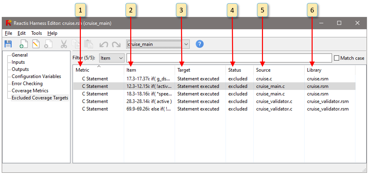
Fig. 6.12 The Excluded Coverage Targets pane of the Reactis Harness Editor.#
The Excluded Coverage Targets pane is shown in Figure 6.12. Each row of this pane contains one target excluded from coverage. There are five data items per target:
Metric The metric measured by the target.
Item A description of the target (a location and source code fragment).
Target A description of the action which causes the target to be covered. For example, if a target’s metric is Condition, then the target will be either Condition true or Condition false.
Status The target status, which is either excluded, or excluded with assertion.
Source The source file
Library The library where the target is located.
6.14. Synchronizing with an RSI File#
Synchronizing the current harness with an .rsi File causes the (external) types of all Inputs, Outputs, and Configuration variables to be updated to match the types in the RSI file. When the Inputs, Outputs, or Configuration Variables pane is selected, the Tools menu will include an option Synchronize with RSI File. Selecting this option will open a dialog which lets you select an .rsi file to synchronize the current harness with.
6.15. Synchronizing with C Code#
Synchronizing the current harness with the C code causes the internal types of nputs, Outputs, and Configuration variables to be updated to match the types in the C Code. This is only necessary when the C code under test has been modified. When the Inputs, Outputs, or Configuration Variables pane is selected, the Tools menu will include an option Synchronize with C Code. Selecting this option will automatically update the internal type of each harness variable to match the type of the variable in the C code.
