3. Reactis Model Inspector Top-Level Window#
This chapter concentrates on the functionality available in the Reactis Model Inspector top-level window.
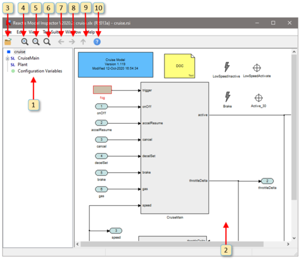
Fig. 3.1 The Reactis Model Inspector top-level window.#
3.1. Labeled Window Items#
An annotated screen shot of the Reactis Model Inspector top-level window may be found in Figure 3.1. This section describes the functionality of the numbered items in this figure, while the section following discusses the workings of the pull-down menus.
The numbers below refer to the labels in Figure 3.1.
The model hierarchy panel shows the subsystems in the model and how they are related. Clicking the + to the left an item displays the subsystems of the item. Clicking on an item causes the diagram for the item to be displayed in the main panel (window
item 2). Pressing the “F2” key causes the parent of the currently displayed system to be displayed. Hovering in the hierarchy panel over a child of the currently displayed system causes the child to be highlighted in the main panel.Right-clicking on an item in the hierarchy panel causes a pop-up menu to be displayed with an entry Copy System Path. Selecting the entry causes the path of the selected subsystem to be copied to the clipboard. The path can then be easily pasted into another document such as a spreadsheet, text file, or email. The copied system path can also help you easily navigate to the appropriate subsystem in the Simulink editor if you decide to modify a portion of the model currently displayed in Reactis Model Inspector. To do so:
a. In the hierarchy panel, right-click on the subsystem of interest and select Copy System Path
b. Start MATLAB and open your model in Simulink
c. At the MATLAB prompt type
open_system('d. Paste in the system path from the clipboard
e. Type
');and hit returnf. The subsystem of interest will be displayed in the Simulink editor
The main panel displays the currently selected Simulink subsystem, Stateflow diagram, C code, or Embedded MATLAB code. You may interact with the diagram in a number of different ways using the mouse including hovering over model items, double-clicking on items, or right-clicking in various parts of the panel. The following mouse operations are available:
Hovering…
over a From or Goto block will cause it and its associated block(s) to be highlighted in yellow.
over a Data Store Read, Data Store Write or Data Store block will cause it and its associated block(s) to be highlighted in yellow.
over a Validator objective will cause its wiring information to be drawn in blue arrows from the data items monitored (or controlled in the case of a virtual source) to the objective.
over a top-level input port that is controlled by a virtual source will show a blue arrow indicating the virtual source block that is controlling this input port.
over a Stateflow transition segment will cause the segment and its label to be highlighted in yellow.
Clicking…
on a signal line in a Simulink system highlights the signal in yellow. This makes it easy to trace a signal back to the point where it was generated and forwards to the point where it is consumed (used by a block to compute a new value). The highlighting flows through (backward and forward) the following blocks that do not modify a signal value: Inport, Outport, Subsystem, From, Goto, Data Store Write, Data Store Read.
in empty space removes signal highlighting.
Double Clicking…
on a Simulink block will display the block’s parameters.
on a Simulink subsystem will cause the subsystem diagram to be displayed in the main panel.
on a Stateflow state will cause the state’s diagram to be displayed in the main panel.
on a Simulink S-Function block with an associated Reactis Makefile (
.rsmfile) will cause the.rsmfile to be displayed in the main panel.on a From, Goto or Goto Tag Visibility block will open a dialog listing all matching From and Goto blocks in your model (see the Lists of Matching From/Goto or Data Store Blocks section).
on a Data Store Read/Write/Memory block will open a dialog listing all matching blocks in your model (see the Lists of Matching From/Goto or Data Store Blocks section).
on a top-level input port will bring up the port type editor (in read-only mode) to inspect the constraint associated with the inport.
on a configuration variable in the Configuration Variable Panel will bring up a type editor dialog (in read-only mode) to inspect that variable’s type constraint.
on a Validator expression objective will open the parameter dialog for that objective (in read-only mode).
Right Clicking…
Causes different pop-up menus to be displayed. The contents of the menu vary based on where the click occurs. A summary of the menu items follows.
Right-Click Location
Menu Entries
Validator objective (i.e. user-defined target, assertion, or virtual source)
View Properties… View properties of the objective.
Simulink block
View Block Parameters… Display Simulink block parameters.
Top-level input port or configuration variable in Configuration Variable Panel
View Type… Inspect type of top-level input port or configuration variable.
Top-level output port or test point Variable Panel
View Tolerance Inspect the tolerance used when comparing the actual value of the top-level output port or test point to its expected value.
When a diagram is too big to display completely in the main panel, scroll bars appear for repositioning the diagram. Alternatively the diagram may be repositioned by left-clicking and dragging in the panel or by using the cursor keys. If your mouse includes a scroll wheel, then you may scroll vertically by clicking in the main panel and then using the scroll wheel.
Left-clicking and dragging in the panel while holding down the control key defines a “print region” that can be used for printing parts of a model. The print region is represented as a shaded blue box; it may be removed using the File -> Remove Print Region menu entry or pressing the escape key.
Finally, pressing the F2 key within this panel causes the parent of the currently displayed subsystem to be displayed, pressing F3 zooms in, and pressing F4 zooms out.
Load a new model into Reactis Model Inspector.
Zoom in.
Zoom out.
Fit to page.
Go back in the history of displayed subsystems.
Go forward in the history of displayed subsystems.
Display the parent of the currently displayed subsystem.
Open Reactis Model Inspector help window.
3.3. Lists of Matching From/Goto or Data Store Blocks#
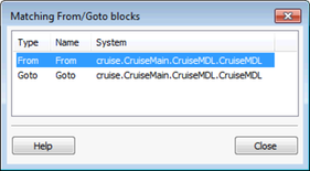
Fig. 3.2 The list of matching From/Goto or Data Store blocks.#
This dialog comes up after double-clicking on a From, Goto, Goto Tag Visibility or Data Store Read/Write/Memory block in Reactis Model Inspector. It lists all other such blocks in your model that match the double-clicked block.
In this dialog you can:
Double-click on a row to have Reactis highlight the block in the main panel. If the block is located in a different subsystem than the one currently displayed, Reactis will switch to that subsystem.
Click on a column header to re-sort the table by the values of that column.
Click on the Close button to close the dialog.
3.4. Configuration Variable Panel#
If the model you are inspecting has configuration variables, Reactis Model Inspector will include an entry Configuration Variables in the top-level of the hierarchy panel. Clicking on this entry displays a block in the main panel for each currently defined configuration variable. This panel allows you to view configuration-variable information. Double-clicking on a configuration variable opens the type editor dialog in read-only mode to inspect a constraint for the configuration variable.
3.5. Printing Models#
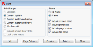
Fig. 3.3 The Print dialog.#
Reactis Model Inspector includes a flexible facility for printing models. Upon selecting menu item File -> Print… the print dialog shown in Figure 3.3 appears. The radio buttons and check-boxes in the Print Range section of the dialog specify which portions of the model should be printed as follows.
- Selection.
Prints only the portion of the model located within the current print region in the main panel. If no print region is defined, this entry is disabled. A print region is selected by left-clicking and dragging in the main panel while holding down the control key. The print region is cleared by selecting menu item File -> Remove Print Region.
- Current system.
Prints only the system currently displayed in the main panel.
- Current system and above.
Prints the system currently displayed in the main panel and all systems between the current system and the top-level system in the current model. Each such system is printed on a separate sheet of paper.
- Current system and below.
Prints the system currently displayed together with all its subsystems, sub-subsystems, etc. Each system is printed on a separate sheet of paper.
- Whole model.
Prints the whole model.
- Expand unique library links.
When checked, library blocks referenced by the model will be printed. Note that each library block is printed only once, even though some blocks might be referenced multiple times by a model.
- Look under masks.
When checked, masked subsystems will be printed.
The following radio buttons and check-boxes in the Frame section specify whether a frame should be printed on each page, and if so what content should be included in the frame.
- No frame.
When checked, no frame is printed.
- Frame.
When checked, a frame is printed.
- Include system name.
When checked, the name of the system is printed in the upper left part of the page frame.
- Include print date.
When checked, the date the model was printed is included in the bottom left corner of the frame on each page.
- Include page number
When checked, the page number is printed in the bottom right corner of the frame on each page.
- Include file name.
When checked, the name of the
.mdlfile containing the model and the folder containing the file is printed in the bottom left corner of each page.
The remaining buttons in the print dialog work as follows.
- Help.
Display print dialog help.
- Page Setup…
Invokes a dialog that allows the user to specify paper size and margins, and whether printing should be portrait or landscape.
- Preview.
Open a viewer to display what will be printed.
- Print…
Begin printing.
- Close.
Close the dialog (and cancel printing).
3.6. Reactis Global Settings#
Selecting File > Global Settings… invokes the Reactis Model Inspector Global Settings dialog, which allows you to adjust some aspects of the way Reactis Model Inspector operates. The global settings are partitioned into four tabbed panes each described in detail below: General, Path, User Info, and License.
3.6.1. General Global Settings#
The General global settings pane shown in Figure 3.4 includes the following items.
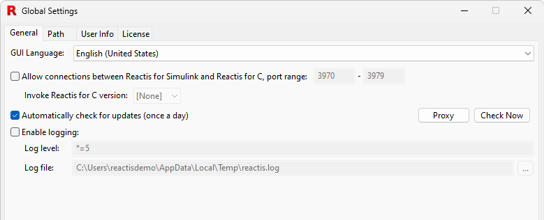
Fig. 3.4 The Global Settings dialog with the General pane selected.#
- GUI Language.
Language used in the Reactis Model Inspector GUI.
- Allow connections between Reactis Model Inspector and Reactis for C.
If enabled, Reactis will a. listen for and respond to incoming link connections from Reactis for C and b. Show the File > Invoke Reactis for C menu item to start and link to Reactis for C.
- Invoke Reactis for C version.
This drop-down box lists installed versions of Reactis for C that support linking. The selected version will be invoked when the user selects File > Invoke Reactis for C.
- Automatically check for updates (once a day).
Instructs Reactis Model Inspector to check once per day whether updates to Reactis Model Inspector are available for download. If updates are found you will be asked if you would like to download and install the patch. Note: this feature can be disabled at install time; in which case this checkbox will not appear in the dialog.
- Enable logging.
Enable logging, specify a log level, and indicate the file to which the log should be written. Note that logging degrades performance and can create very large log files; therefore, it is typically only used to diagnose problems. The log level string will be provided by the Reactive Systems support team if you are asked to create a log file.
3.6.2. Path Global Settings#
The Path pane of the Global Settings dialog, shown in
Figure 3.5, enables you to specify
the list of folders in which
Reactis Model Inspector will search for files such as Simulink model libraries (.slx).
The order in
which folders are listed in the dialog specifies the search order (from top
to bottom).
Note that Reactis also gives users the capability to define model-specific search paths which consist of a list of folders to be searched when loading a given model. The model-specific path can be viewed in Reactis Model Inspector by selecting Edit > Search Path…. When searching for files, the complete search path is constructed by prepending the model-specific path to the global path.
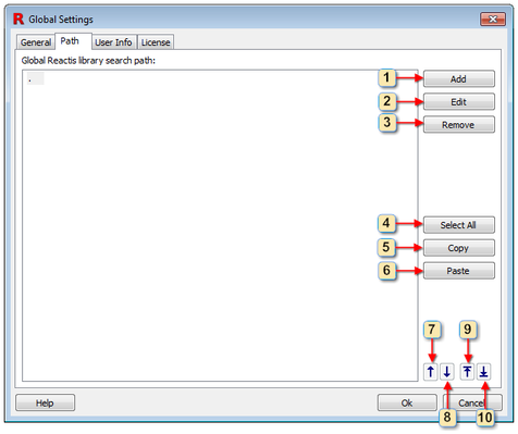
Fig. 3.5 The Global Settings dialog with the Path pane selected.#
The buttons labeled in the figure work as follows.
Add a new folder to the list.
Open a dialog to edit the currently selected folder.
Remove the currently selected folder(s) from the list.
Select all folders in the list.
Copy the currently selected folder(s) to the clipboard.
Paste from the clipboard to the list.
Move the currently selected folder up one spot in the list.
Move the currently selected folder down one spot in the list.
Move the currently selected folder to the top of the list.
Move the currently selected folder to the bottom of the list.
3.6.3. User Info Global Settings#
The User Info pane is shown in Figure 3.6. When Reactis Model Inspector is configured to use a remote license server as described in the next section, information contained in this panel is submitted to the server when Reactis Model Inspector is started, and available to all users who have access to the server.
The list of users occupying licenses at a given time may be obtained using the License pane of the Global Settings dialog as described below, or using the standalone License Monitor utility included in the Reactis License Manager distribution. This utility may be invoked from the Windows Start menu.
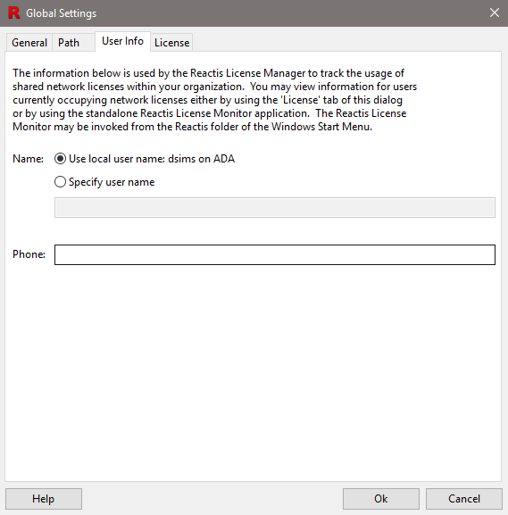
Fig. 3.6 The Global Settings dialog with the User Info pane selected.#
3.6.4. License Global Settings#
The License pane, shown in Figure 3.7, enables you to query and specify license configuration information. The first two sections display the MAC address of the machine on which Reactis Model Inspector is running and the location of a local license file if one is in use.
The third section of the pane displays a list of servers running the Reactis License Manager. When Reactis Model Inspector is invoked, this list will be searched from top to bottom for an available license. The lowest portion of the pane displays a list of users currently using licenses for the License Manager/product currently selected in the License servers list.
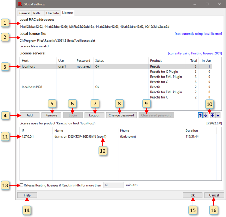
Fig. 3.7 The Global Settings dialog with the License pane selected.#
Each of the window items labeled in Figure 3.7 is interpreted and used as follows.
The MAC address of the computer on which the Reactis is running.
Information about the contents of the local license file. If there is a problem with the license file, then a description of the error condition is listed here. If no problem exists, then a list of licensed products and their expiration dates is given.
The list of servers running the Reactis License Manager. Each entry in the list includes the following:
- Host
The name or IP address of the server running the License Manager.
If access control is enabled by a Reactis License Manager, then users must provide a username and password to authenticate and request a license.
- User
Username of the person requesting a license.
- Password
Password for the person requesting a license.
- Status
The status of the connection to the License Manager.
For each product managed by the server:
- Product
Name of the product (Reactis, Reactis for C Plugin, Reactis Model Inspector, Reactis for C).
- Total
The total number of licenses for the product.
- In Use
The number of currently occupied licenses for the product.
Add a new License Manager to the list.
Remove the currently selected License Manager from the list.
Log in to the License Manager.
Log out of the License Manager.
Change the password of the current user that is logged in.
Clear the saved password for the current user, requiring the user to enter password on next attempt to login.
Move the currently selected License Manager up one spot in the list, down one spot in the list, to the top of the list, or to the bottom of the list. These buttons are only enabled when the list contains more than one License Manager.
Information regarding the currently selected License Manager is displayed here. If there is a problem with the connection to the License Manager, then a description of the error condition is listed here. If no problem exists, then for each license currently occupied, this section lists:
- IP Address.
The IP address of the computer on which the Reactis application occupying the license is running.
- Name.
The contents of the Name field in the User Info pane of the person occupying the license.
- Phone.
The contents of the Phone field in the User Info pane of the person occupying the license.
- Duration.
The length of the time this computer has been holding the license.
The username for the user that is logged in.
Check box to activate the release of a floating license that is idle for a predetermined number of minutes.
View the Reactis License Manager documentation.
Close the window and save changes made to the list of monitored servers.
Close the window without saving any changes made to the list of monitored servers.
3.7. Model Comments#
Model Comments gives you a mechanism for annotating a model under test without making any changes to the model itself. To insert a comment:
Select a subsystem in the Reactis hierarchy panel where the comment should reside
In the Reactis main panel, right-click at the location you prefer to place the comment and select Add Comment…
In the resulting dialog enter the desired comment text (and perhaps an optional comment name)
After a comment is inserted in a model, it appears as a yellow rectangle with the upper right corner folded (somewhat like a sticky note). You can do the following with model comments:
Create a new comment in any subsystem of a model.
View a comment which was previously added.
Edit and make revisions to a comment.
Move or resize a comment.
Cut, or Copy a comment to the clipboard.
Paste a comment from the clipboard.
Remove a comment.
3.7.1. Adding a Comment#
To add a comment, right click in empty space in the main panel, then select Add Comment…. This will open an instance of the Comment Editor, which will be similar in appearance to Figure Figure 3.8.
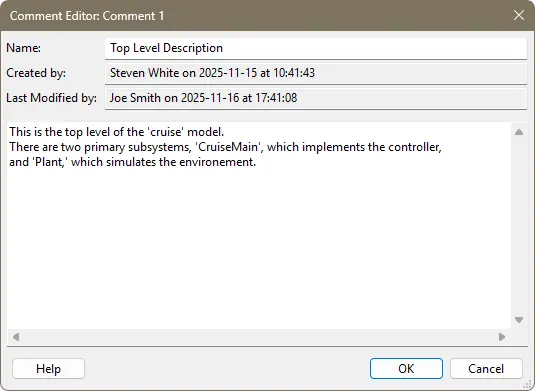
Fig. 3.8 The Comment Editor.#
There are four values displayed in the main panel of the Comment Editor:
Name. The name of the comment. This is optional and can be left empty. Comment names are not required to be unique.
Created by. The user who created the comment and the time when it was created. This is automatically filled in by Reactis and cannot be changed. The user name is taken from Reactis’ global settings.
Last Modified by.The user who last modified the comment and the time when it was modified. This is automatically filled in by Reactis and cannot be changed. The user name is taken from Reactis’ global settings.
The comment text. The large area where you enter the comment text.
There are two ways to close the Comment Editor. Click on OK if you are satisfied with the comment and want to save it. Click on Cancel to close the editor without saving.
3.7.2. Viewing Comments#
Once a comment has been created, it will appear as a sticky note at the point where you right clicked. To quickly view the comment, hover over it with the mouse and a tooltip will appear with comment text, as shown in Figure Figure 3.9. Note that when the comment is viewed this way, it will be clipped if it is large.
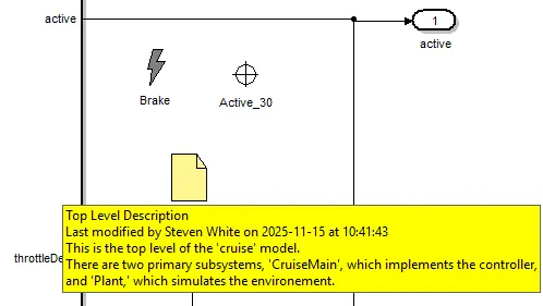
Fig. 3.9 Viewing a comment by hovering over it.#
You can also view the comment by double-clicking on it or right-clicking on it and selecting Edit Comment…. This will open the Comment Editor. You can then see the entire comment in the editor, and close the editor when you are finished reading the comment.
3.7.3. Editing Comments#
To edit a comment, right click on it and select Edit Comment… from the pop up menu. This will open the Comment Editor. In the editor, can change the name and text of the comment as desired, then click on OK to save the changes, or Cancel to close the editor without saving.
3.7.4. Moving and Resizing Comments#
To move a comment within the current displayed subsystem, left-click on it and drag it.
To resize a comment, first left-click on it to cause a blue border to appear around the edges of the comment. This border includes eight blue squares, one on each corner and one in the middle of each border. Left-click on a blue square and drag to resize the comment.
3.7.5. Copying, Cutting, and Pasting Comments#
If you want to move a comment to a different subsystem, you will need to cut the comment from its current subsystem, then navigate to the subsystem where you want to place the comment and paste it there.
To copy a comment to the clipboard, right click on and select Copy from the pop up menu that appears. This will copy the comment to the clipboard.
To cut a comment from the model, right click on it and select Cut from the pop up menu. This will copy the comment to the clipboard and remove it from the model.
To paste a comment from the clipboard, right click on the location where you want the comment to appear and select Paste from the pop up menu. This will create a comment identical to the comment stored in the clipboard, with the exception that the time of last modification and the user name who performed the last modification will be updated.
Note that you can paste as many copies of a comment as you wish.
3.7.6. Removing Comments#
To remove a comment, right click on it and select Remove from the pop up menu.
The comment will disappear from the main panel and removed from the .rsi file.
3.7.7. Undoing Changes to a Comment#
All comment changes can be undone by clicking on the Undo icon in the toolbar.
Comment changes which were previously undone can be restored by clicking on the
Redo icon. When the .rsi file is saved, all changes become permanent and cannot
be undone, so be careful when saving the .rsi file.
3.7.8. Comment ID Numbers#
Reactis automatically assigns a unique ID number to each comment. These are used to identify comments which would otherwise be identical. When a comment is edited, the ID number is displayed in the title bar of the Comment Editor.